
Method for attaching radar for vehicle, radar for vehicle, and monitoring method

a technology for attaching radar and vehicles, which is applied in the direction of antennas, instruments, and movable body antenna adaptation, etc., can solve the problems of degrading the detection accuracy of radar b>1/b> for vehicles, and achieve the effect of reducing the impact of reflection wave from the road surface and accurately monitoring an obj

Active Publication Date: 2005-03-24
FUJITSU GENERAL LTD
View PDF19 Cites 17 Cited by
  • Summary
  • Abstract
  • Description
  • Claims
  • Application Information

AI Technical Summary

Benefits of technology

[0009] The invention is made to solve the above-mentioned problem. In order to eliminate the blind spot caused in radar having sharp horizontal directivity, the invention provides radar having low horizontal directivity. Also, the invention provides an attachment method for attaching the radar having low horizontal directivity onto a vehicle.
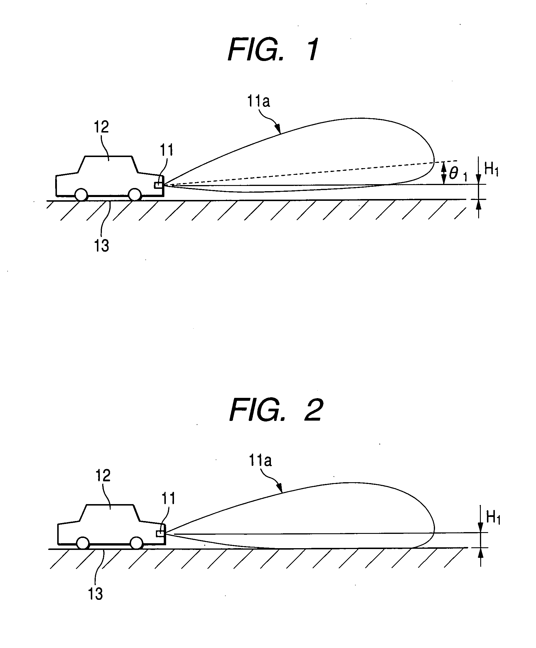
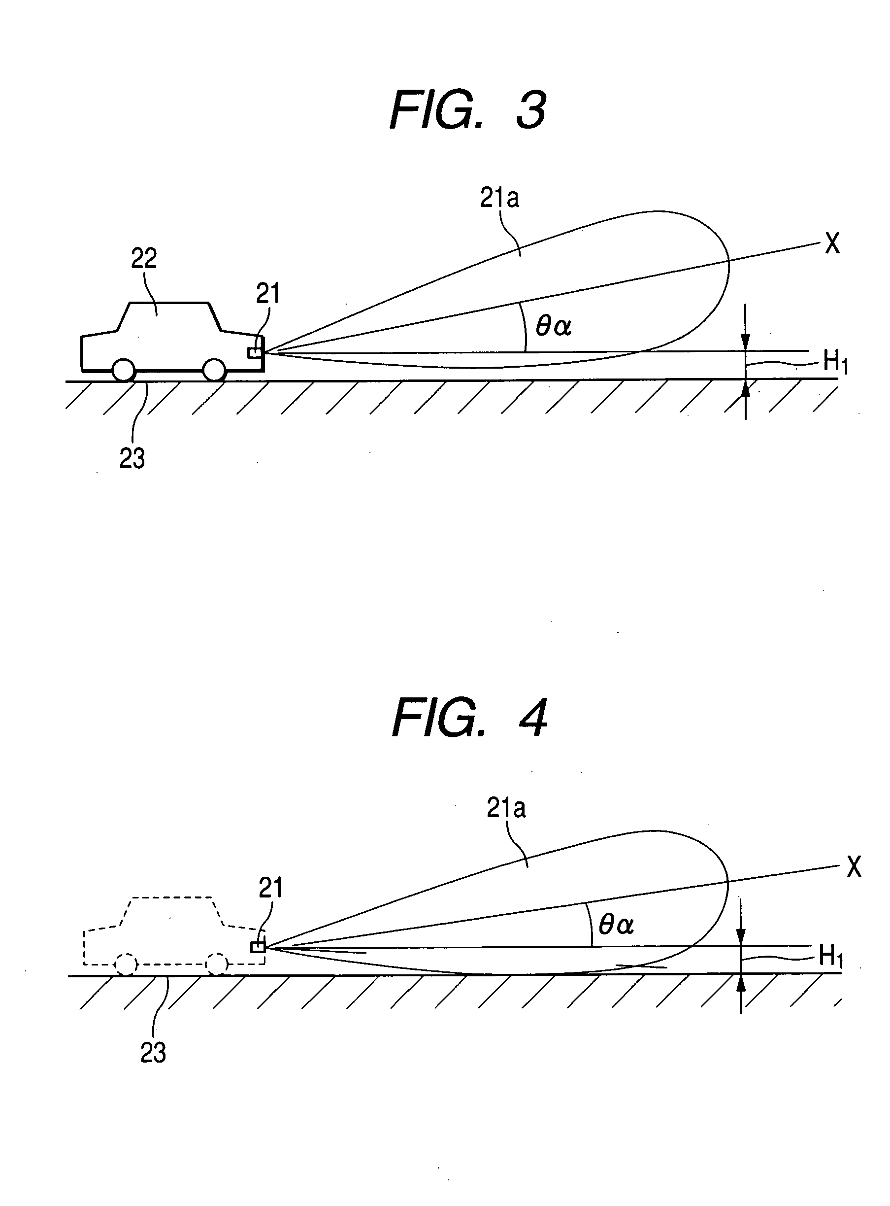
[0014] On the contrary, the method for attaching the radar for vehicle attaches the radar to the vehicle so that the axis of the directivity pattern of the antenna directs upward with respect to the horizontal direction. Therefore, the affect of the reflection wave from the road surface can be reduced to be very small. Thereby, detection accuracy of the radar for vehicle can be improved.
[0018] Therefore, with the radar for vehicle, the same effect can be obtained as the case where a radar for vehicle is attached to a vehicle in accordance with the method for attaching the radar for vehicle so that the axis of the directivity pattern of the antenna directs upward with respect to the horizontal direction. That is, affect of the reflection wave from the road surface can be reduced drastically. Thereby, the detection accuracy of the radar for vehicle can be improved.
[0019] Also, there is no need to attach the radar for vehicle while adjusting the directivity of the antenna to direct upward. Therefore, the operation for attaching the radar for vehicle can be simplified.
[0021] Since the axis of the directivity pattern directing upward with respect to the horizontal direction, the same effect can be obtained as the radar for vehicle. That is, the affect of the reflection wave from the road surface can be reduced drastically. Therefore, the monitoring method can monitor an object accurately.

Problems solved by technology

Therefore, a reflection wave from the road surface has great affect, so that there is a fear that the detection accuracy of the radar 1 for vehicle might degrade.

Method used


Image

  • Method for attaching radar for vehicle, radar for vehicle, and monitoring method
  • Method for attaching radar for vehicle, radar for vehicle, and monitoring method
  • Method for attaching radar for vehicle, radar for vehicle, and monitoring method

Examples


modified example

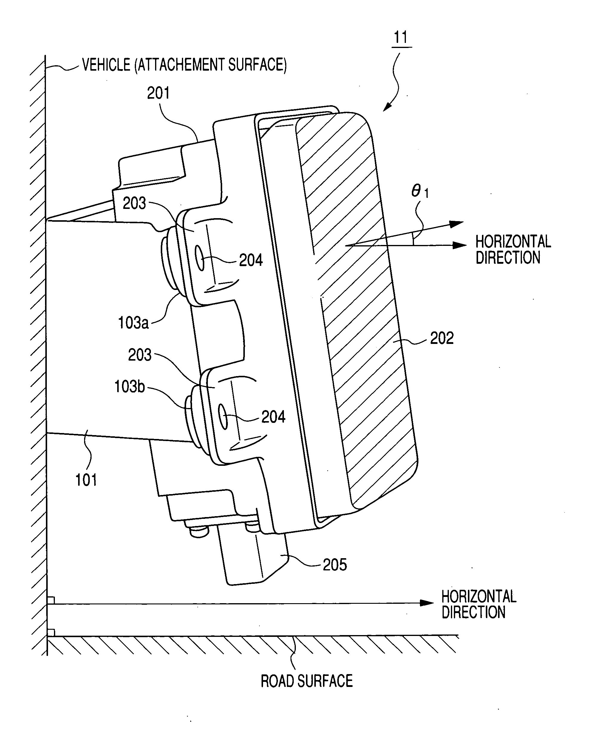
[0061] Next, with reference to FIG. 13, a modified example of the bracket 100 and the casing 201 will be described. In the embodiment (2), θ1 is the angle between the surface in which the screw holes 104 of the protrusion pieces 103a, 103b are defined and the bottom plate 105. However, in the modified example, the surfaces in which the screw holes 104 are defined and the bottom plate 105 are parallel. Also, in the embodiment (2), the surfaces in which the screw holes 204 are defined (the surfaces on a side of the electric-wave emission surface and those on a side of the bracket) are parallel. However, the modified example is also different in this point. The casing 201 includes the protrusion pieces 203a, 203b having different thickness. The protrusion pieces 203a, 203b get thinner as advancing in an arrow A direction. For example, an angle between a shaded surface of the protrusion piece 203a (one of the surfaces in which the screw hole 204 is defined) and a surface of the protrusi...


PUM


Abstract

An attachment method attaches a bracket to a vehicle, and attaches a radar to the bracket so that an axis of a directivity pattern of an antenna directs upward with respect to a horizontal direction. The antenna of the radar has an asymmetric vertical directivity pattern with respect to the axis of the directivity pattern.

Description

BACKGROUND OF THE INVENTION [0001] 1. Field of the Invention [0002] The present invention relates to a method for attaching a radar for vehicle (Radar: Radio detecting and ranging), and a radar for vehicle. In more detail, the invention relates to an attachment method for attaching onto a vehicle in a proper manner a radar for vehicle that monitors front sight and rear sight of the vehicle, and to the radar for vehicle. [0003] 2. Description of the Related Art [0004] In a conventional system for assisting driving of vehicles, a distance between oneself and a vehicle ahead and a relative speed therebetween are measured with using radar. Also, the conventional assisting system controls the vehicle to keep the distance between oneself and the vehicle ahead based on those measurement values. [0005]FIG. 5 is a schematic diagram showing a state where conventional radar for vehicle is used. In FIG. 5, reference numeral 1 designates the radar for vehicle. An antenna (not shown) of the radar...

Claims


Application Information

Patent Timeline
IPC IPC(8): G01S7/03G01S7/28G01S13/60G01S13/931H01Q1/12H01Q1/32
CPCG01S7/03G01S7/2813G01S13/931H01Q1/3283G01S2013/9389H01Q1/1221H01Q1/3233G01S2013/462G01S2013/93275
Inventor KAKISHITA, ETSUOYAMADA, YUKINORITANAKA, YUICHIMIZUNO, HIROSHI
Owner FUJITSU GENERAL LTD
Learn More