Video user interface system and method

Inactive Publication Date: 2005-03-24
SENSORMATIC ELECTRONICS CORP
View PDF15 Cites 17 Cited by
  • Summary
  • Abstract
  • Description
  • Claims
  • Application Information

AI Technical Summary

Benefits of technology

The invention avoids the drawbacks of the prior art by providing a graphical user interface that may, according to one aspect of the invention, include one or more panoramic views of a monitored area, one or more virtual views preferably corresponding to portions of the monitored area, and/or reference data such as a reference window overlaid in a panoramic view to identify a portion of the panoramic view corresponding to a virtual view. Panoramic views of the invention, which may be derived from wide-angle lens

Problems solved by technology

One shortcoming of such conventional systems is that they do not conveniently enable a user to discern the part of the monitored area represented by the displayed portion.
Without an image of the entire room or lot and an indication of the area represented by the close-up image, it may be difficult or impossible to quickly determine the position of the person or object in the monitored room or lot.
This is espec

Method used


Image

  • Video user interface system and method
  • Video user interface system and method
  • Video user interface system and method

Examples


Embodiment Construction

User Interface

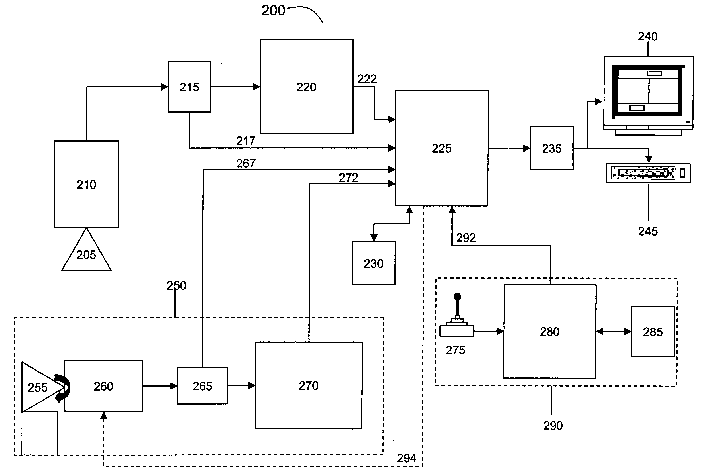
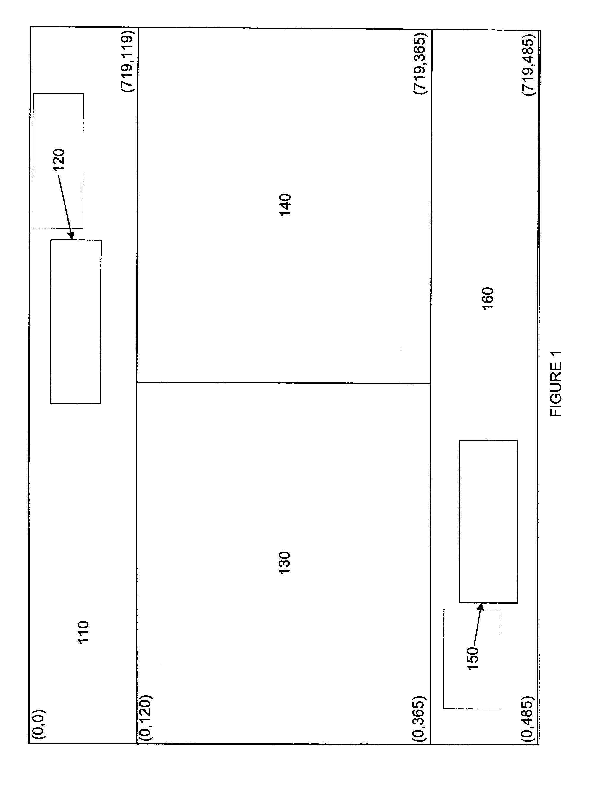
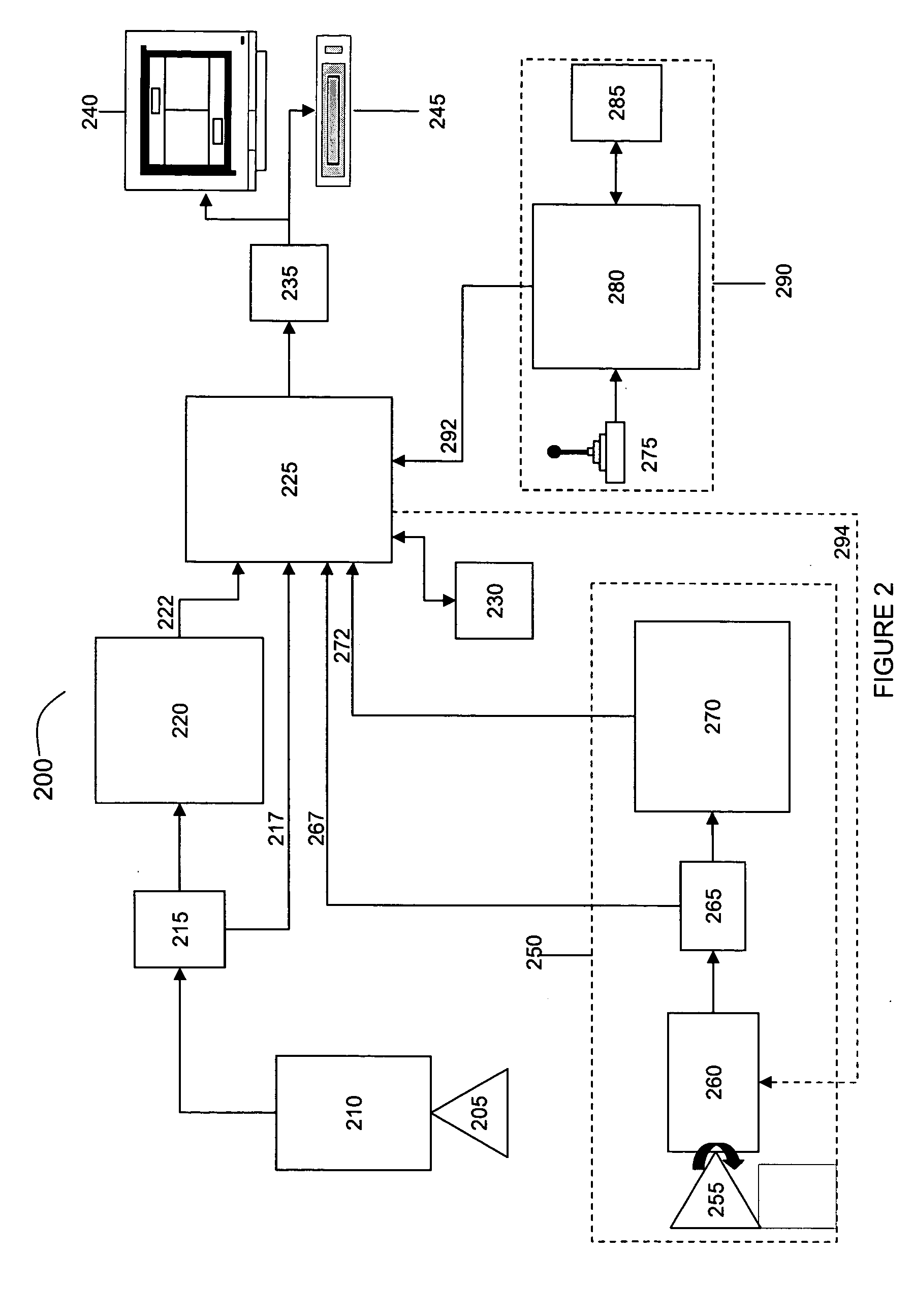
An exemplary system in accordance with the invention includes a processor configured to transform digital image data corresponding to the wide-angle images, such as video images, of a monitored area into data corresponding to one or more panoramic views of the monitored area. Referring to FIG. 1, a user interface in accordance with an exemplary implementation of the invention is conceptually shown. Strips 110 and 160, which may be rectangular in shape as illustrated, correspond to transformed panoramic views. The transformed panoramic views 110 and 160 exhibit upright orientation and substantially reduced (or no) wide-angle image distortion, thus providing a readily discernible view of the monitored area. Examples of a suitable transformation carried out by the processor are discussed subsequently.

The processor is also configured to provide data corresponding to one or more virtual views 130 and 140, each of which is an undistorted (or substantially undistorted) vi...


PUM


Abstract

A video user interface display includes transformed panoramic views of a monitored area, and virtual views of portions of the monitored area. A virtual view may be based upon transformed wide-angle lens image data, or image data from a dome camera system without a wide-angle lens. The transformed panoramic views are derived from wide-angle lens image data, exhibit upright orientation and substantially reduced (or no) wide-angle image distortion, thus providing a readily discernible view of the monitored area. Reference windows overlaid in the panoramic views identify the portions of the panoramic views represented by the virtual views. The virtual views and reference windows respond to operator commands.

Description

BACKGROUND OF THE INVENTION 1. Field of the Invention This invention generally relates to imaging systems, and more particularly, to a system and method for generating a graphical user interface from image data, such as video images. 2. Background Description Conventional video surveillance systems allow users to view portions of monitored areas by either physically aiming a video camera at a desired portion or by generating a perspective corrected view of the desired portion from a wide angle (e.g., fisheye) image of the monitored area. One shortcoming of such conventional systems is that they do not conveniently enable a user to discern the part of the monitored area represented by the displayed portion. For example, a video surveillance system may display a close-up image of a person or an object (the displayed portion) in a room or a parking lot (the monitored area). Without an image of the entire room or lot and an indication of the area represented by the close-up image, i...

Claims


Application Information

Patent Timeline
IPC IPC(8): G06F3/048H04N5/232H04N7/18
CPCG06F3/04815G08B13/19628G08B13/19682G08B13/19689H04N7/181H04N5/232H04N5/23216H04N5/23238G08B13/19691H04N23/62H04N23/698H04N23/635H04N23/695
Inventor MILLS, LAWRENCE R.
Owner SENSORMATIC ELECTRONICS CORP
Why Eureka
Try Eureka