Exposure apparatus and exposure method

a technology of exposure apparatus and exposure method, which is applied in the field of exposure apparatus, can solve the problems of inability to achieve high degree of accuracy in the pattern on each layer, inability to adjust the distortion of the image to be drawn, and inability to achieve the effect of fineness of the pattern

Active Publication Date: 2005-09-29
ADTEC ENG +1
View PDF2 Cites 16 Cited by
  • Summary
  • Abstract
  • Description
  • Claims
  • Application Information

AI Technical Summary

Benefits of technology

[0011] In view of the aforementioned circumstances, the present invention provides an exposure apparatus and method that can reduce distortion of an image to be drawn (formed) on a recording medium by detecting zigzag movement caused by movement of a recording stage, for each of positions of recording heads.

Problems solved by technology

However, the fineness of a pattern to be recorded on PWB or FPD (a wiring pattern) becomes higher accompanied by high density packaging of parts, and a problem about displacement of a recording position caused along with expansion and contraction of a mask has become apparent.
For example, when a multi-layer printed wiring board is used, alignment of a hole such as a through hole formed on a substrate, and a pattern on each of the layers cannot be carried out with a high degree of accuracy.
Accordingly, a problem arises that the fineness of a pattern cannot be made higher.
However, in the aforementioned conventional laser-scanning exposure apparatus, when the recording stage is moved for drawing a pattern on a recording medium, this movement causes zigzag movement of the recording stage and displacement occurs on the recording stage.
As a result, there is a problem that distortion is caused in the pattern drawn on the recording medium.
However, when the recording stage is moved, zigzag movement, which varies delicately at different positions, occurs on the recording stage due to yawing movement (i.e., the behavior of the recording stage in a direction in which it is moved).
However, if the number of cameras used for recording the behavior increases, the manufacturing cost increases.

Method used


Image

  • Exposure apparatus and exposure method
  • Exposure apparatus and exposure method
  • Exposure apparatus and exposure method

Examples


first embodiment

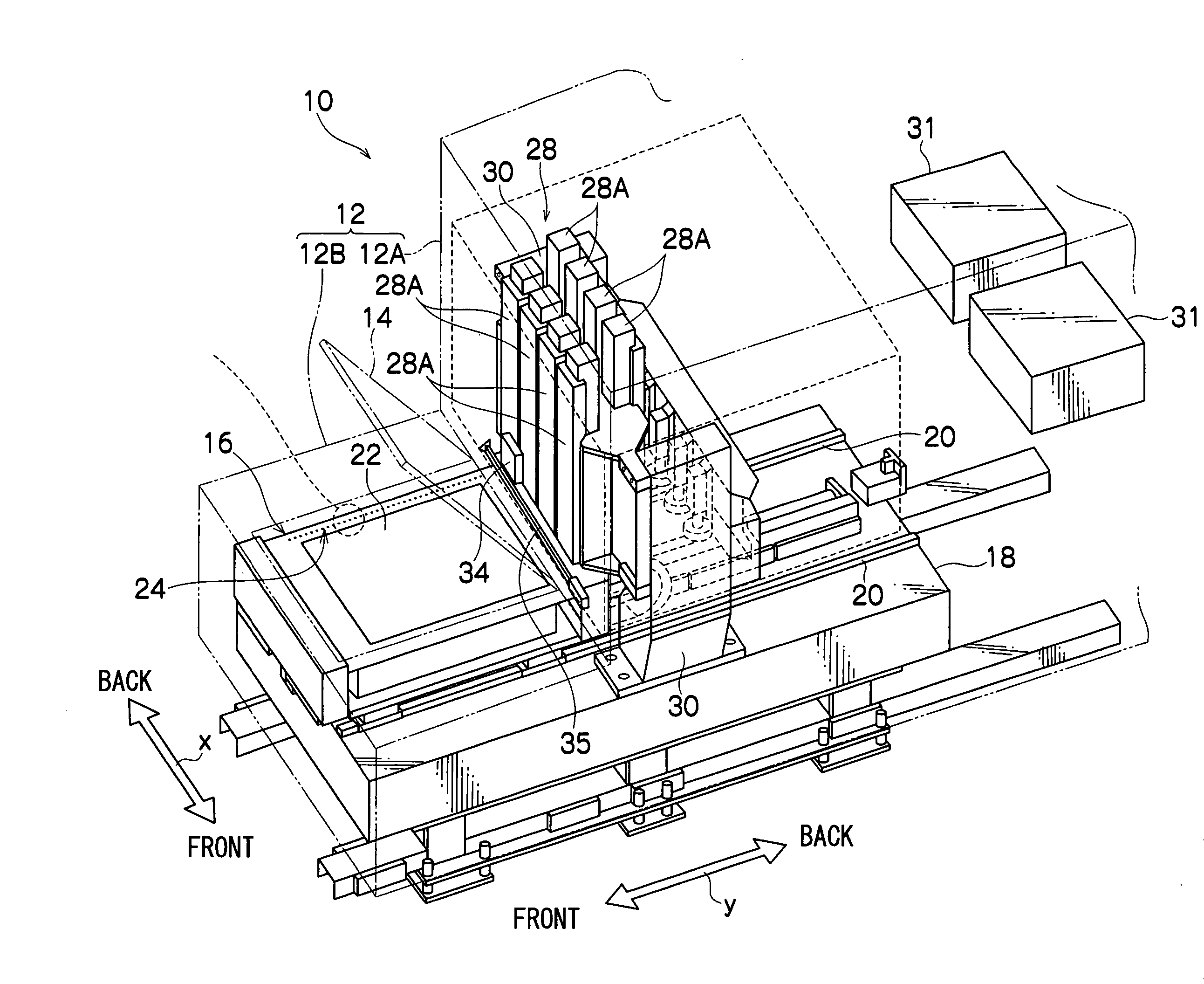
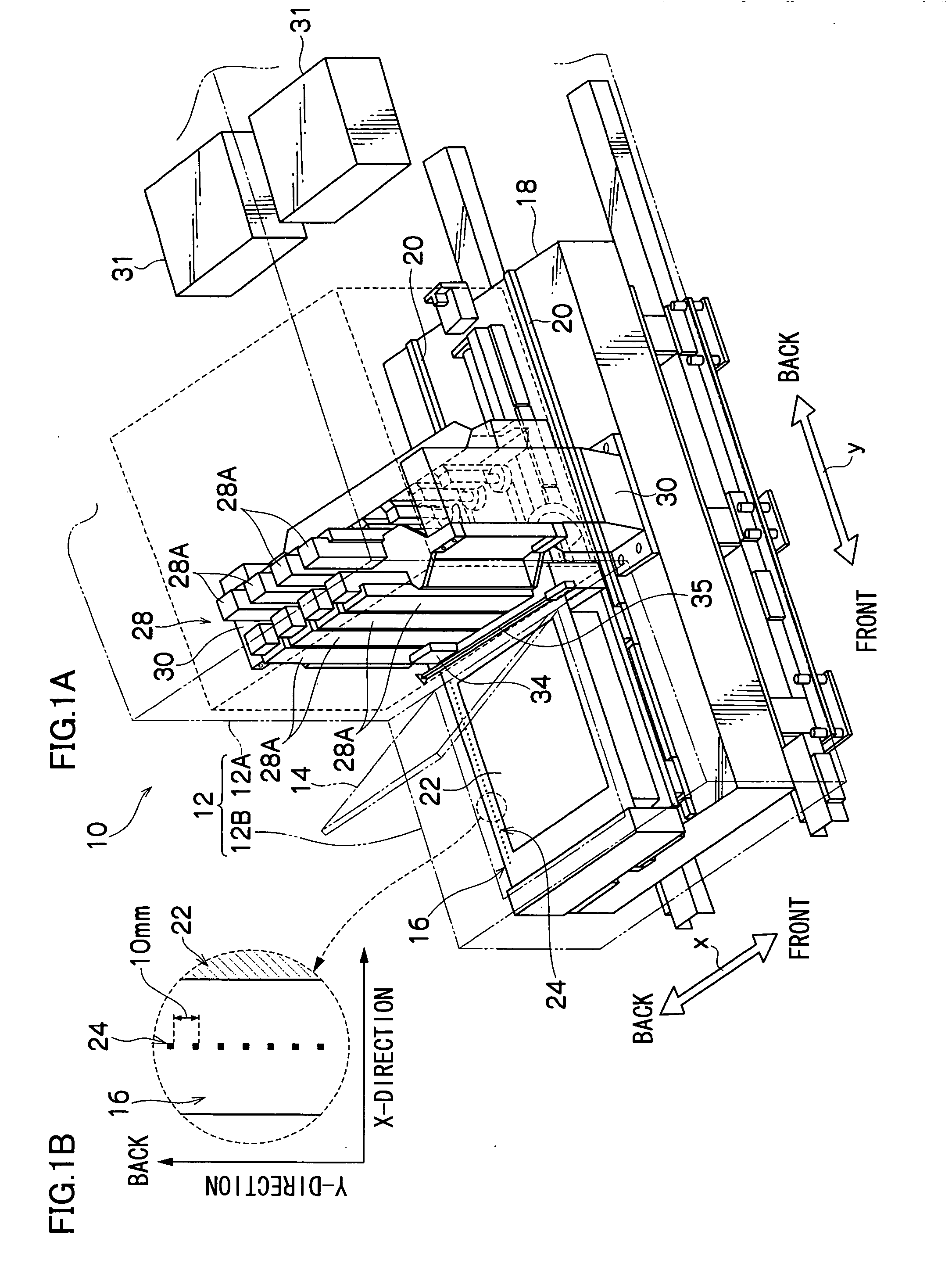
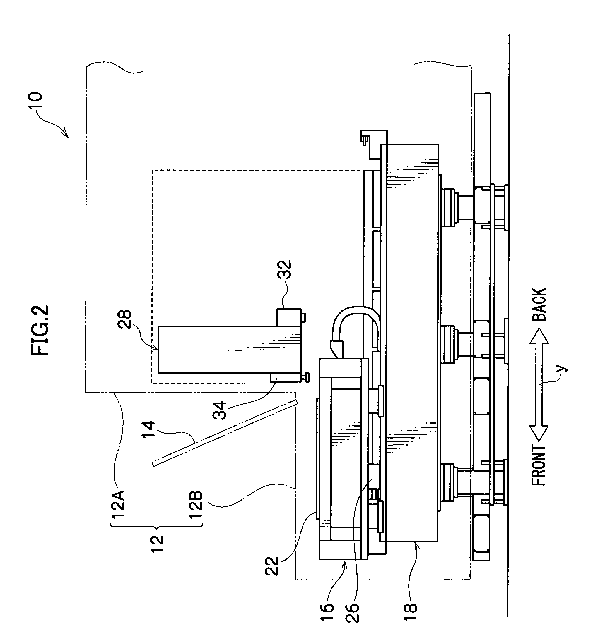
[0094]FIG. 1A and FIG. 2 show a flatbed type exposure apparatus 10 according to a first embodiment of the present invention.

[0095] The exposure apparatus 10 is structured in such a manner that various parts are accommodated in a rectangular frame body 12 that is formed by assembling bar-shaped square pipes in the form of a frame. The frame body 12 is shut off between the inside and outside thereof by attaching a panel (not shown) thereto.

[0096] The frame body 12 is formed by a long tall housing portion 12A, and a stage portion 12B provided so as to project from one side surface of the housing portion 12A.

[0097] The stage portion 12B is provided so that the upper surface thereof is lower that the housing portion 12A. When an operator stands in front of the stage portion 12B, the upper surface of the stage portion 12B is positioned substantially at the height of the operator's waist.

[0098] An opening and closing cover 14 is provided on the upper surface of the stage portion 12B. A...

second embodiment

[0165] Next, a second embodiment of the present invention will be described. The second embodiment is characterized in that the exposure apparatus 10 is used to form a pattern image for acquiring position data by exposure, detect a shift amount of displacement caused by zigzag movement by measuring the obtained pattern image, and register the detected shift amount in the shift-amount calculating section 104.

[0166] An exposure apparatus 10 of the second embodiment is not provided with the CCD camera 34 and the rail 35. Other parts of the exposure apparatus 10 are the same as those of FIGS. 1 and 2, and therefore, a description thereof will be omitted.

[0167]FIG. 15 shows a functional diagram of the second embodiment. Note that the same parts as those of FIG. 7 in the first embodiment will be denoted by the same reference numerals, and therefore, a description thereof will be omitted and only different parts will be described below.

[0168] A pattern input section 140 is connected to ...

third embodiment

[0180] Next, a third embodiment of the present invention will be described. The third embodiment is characterized in that respective shift amounts of displacement in the moving direction and displacement in a direction intersecting the moving direction in relation to a stage surface of the exposure stage 16, which displacements are caused by pitching vibration occurring together with zigzag movement of the exposure stage 16, are detected, and based on the detected shift-amount data, an image represented by image data is corrected both in the moving direction and the intersecting direction.

[0181] In the exposure apparatus 10 according to the third embodiment, the markings 24 are arranged along the y-direction at predetermined intervals (in the third embodiment, at intervals of 50.0 mm), and other structures are the same as those shown in FIGS. 1 and 2 of the first embodiment, and therefore, a description thereof will be omitted.

[0182] Since the markings 24 are arranged at intervals...


PUM

PropertyMeasurementUnit
distanceaaaaaaaaaa
distanceaaaaaaaaaa
sizeaaaaaaaaaa

Abstract

An exposure apparatus and method in which an image is formed on a recording medium mounted on a recording stage by irradiating a light beam based on image data from a recording head while the recording head and the recording stage are relatively moved, in the exposure apparatus and method, storing in advance, in a storage section, shift-amount data of a detected displacement of an image-form position with respect to a stage surface of the recording stage in a direction intersecting a direction in which the recording stage moves, which displacement occurs accompanied by movement of the recording stage; carrying out shifting for each of pixels of an image formed by the image data based on the shift-amount data stored in the storage section; and controlling exposure for the recording medium based on image data of the shifted image, is provided to reduce distortion of the image.

Description

CROSS-REFERENCE TO RELATED APPLICATION [0001] This application claims priority under 35 USC 119 from Japanese Patent Application No. 2004-096565, the disclosure of which is incorporated by reference herein. BACKGROUND OF THE INVENTION [0002] 1. Field of the Invention [0003] The present invention relates to an exposure apparatus that corrects distortion of an image caused by zigzag movement of a recording stage, which zigzag movement occurs due to movement of the recording stage in exposure processing. [0004] 2. Description of the Related Art [0005] Conventionally, as an apparatus in which a predetermined pattern is recorded on a substrate of a recording medium, for example, a printed wiring board (hereinafter referred to as “PWB”) or a flat panel display (hereinafter referred to as “FPD”), a surface exposure apparatus using a mask has been widely used. [0006] However, the fineness of a pattern to be recorded on PWB or FPD (a wiring pattern) becomes higher accompanied by high density...

Claims


Application Information

Patent Timeline
Patent Type & Authority Applications(United States)
IPC IPC(8): G03B27/52
CPCG03B27/52G03F7/70725G03F7/70275G03F7/70258B23D45/061B23D47/025B23D47/042
Inventor KATAYAMA, TORUNAKAYA, DAISUKEJOGO, NAOZUMI
Owner ADTEC ENG
Why Eureka
Try Eureka