
Image pickup apparatus, camera module, electronic device, and fabrication method for image pickup apparatus

a technology of image pickup and fabrication method, which is applied in the direction of optical radiation measurement, instruments, television systems, etc., can solve the problems of warpage or twisting reduction of thickness and weight, and so as to reduce the distortion of image pickup elements, improve the performance of wire bonding, and improve the effect of wire bonding performan

Inactive Publication Date: 2007-08-30
SONY CORP
View PDF15 Cites 18 Cited by
  • Summary
  • Abstract
  • Description
  • Claims
  • Application Information

AI Technical Summary

Benefits of technology

[0006] Therefore, it is demanded to provide an image pickup apparatus, a camera module, an electronic device, and a fabrication method for an image pickup apparatus by which enhancement of the reliability, miniaturization, reduction in thickness and reduction in weight can be achieved advantageously.
[0011] With the image pickup apparatus, camera module, electronic device, and fabrication method for an image pickup apparatus, even if a material having a small thickness and a low rigidity is used for the wiring board of the image pickup apparatus, flatness of the wiring board may be obtained without suffering from warpage or twist. This is advantageous in achievement of reduction of distortion of the image pickup element, assurance of enhancement of the wire bonding performance, and enhancement of the soldering coupling performance and also in enhancement of the reliability, miniaturization, reduction in thickness and reduction in weight of the image pickup apparatus.

Problems solved by technology

However, in the image pickup apparatus in related art, if the wiring board is formed with a small thickness from a material having low rigidity in order to achieve miniaturization, reduction in thickness and reduction in weight, then warpage or twist is likely to occur with the wiring board upon adhesion.
Such warpage or twist gives rise to such disadvantages as distortion of the image pickup element, deterioration of the wire bonding performance and deterioration of the soldering performance of the wiring board.

Method used


Image

  • Image pickup apparatus, camera module, electronic device, and fabrication method for image pickup apparatus
  • Image pickup apparatus, camera module, electronic device, and fabrication method for image pickup apparatus
  • Image pickup apparatus, camera module, electronic device, and fabrication method for image pickup apparatus

Examples


Embodiment Construction

[0019] A preferred embodiment of the present invention is described below with reference to the accompanying drawings.

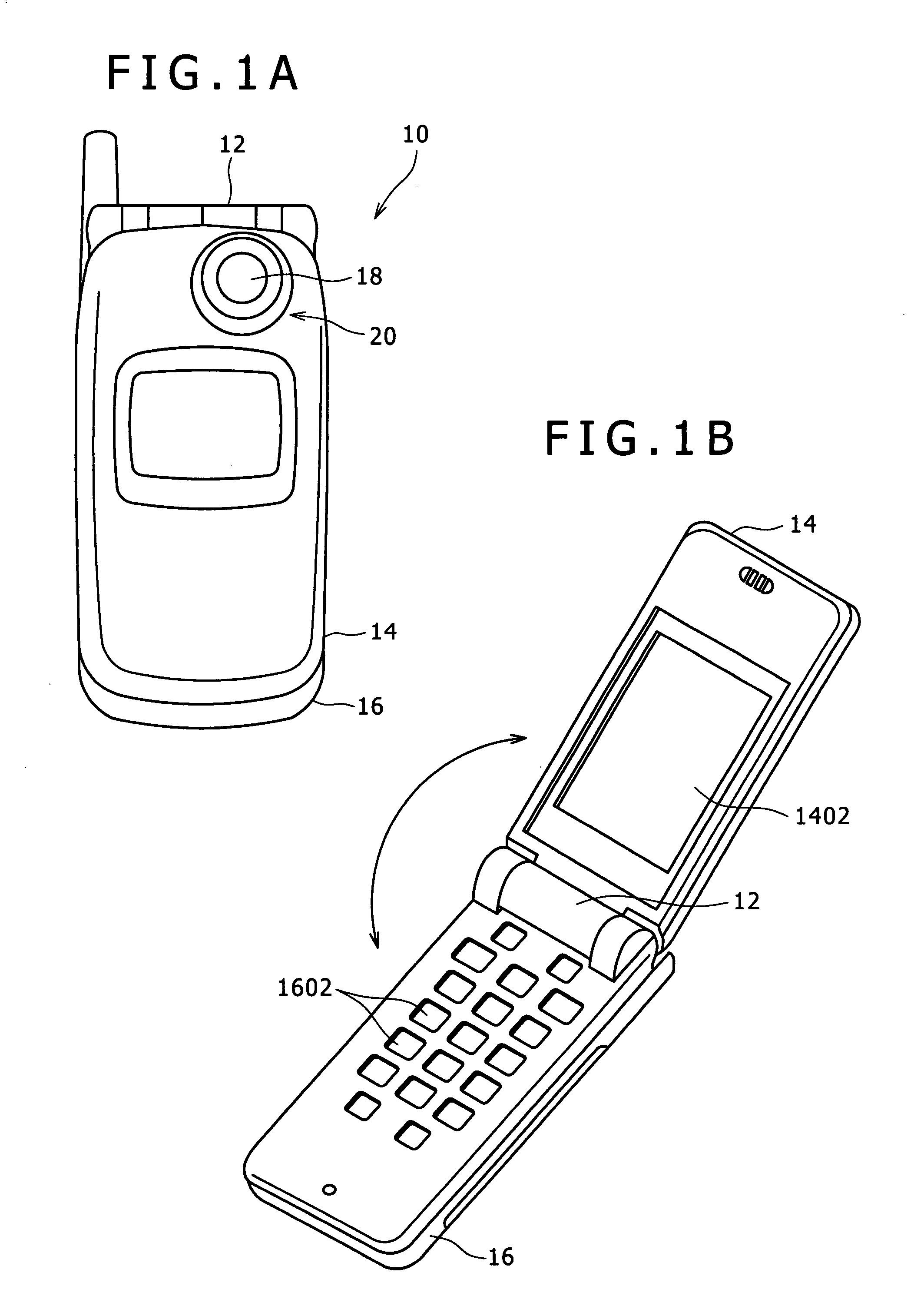
[0020]FIGS. 1A and 1B show an appearance of a portable telephone set 10 which is an electronic device in which a camera module is incorporated.

[0021] Referring to FIGS. 1A and 1B, the portable telephone set 10 shown includes first and second housings 14 and 16 connected for rocking motion relative to each other by a hinge member 12.

[0022] A liquid crystal display panel 1402 is provided on an inner face of the first housing 14 while operation switches 1602 such as ten keys and function keys are provided on an inner face of the second housing 16.

[0023] The camera module 20 is incorporated at a base end portion of the first housing 14, and an image picked up by the camera module 20 is displayed on the liquid crystal display panel 1402.

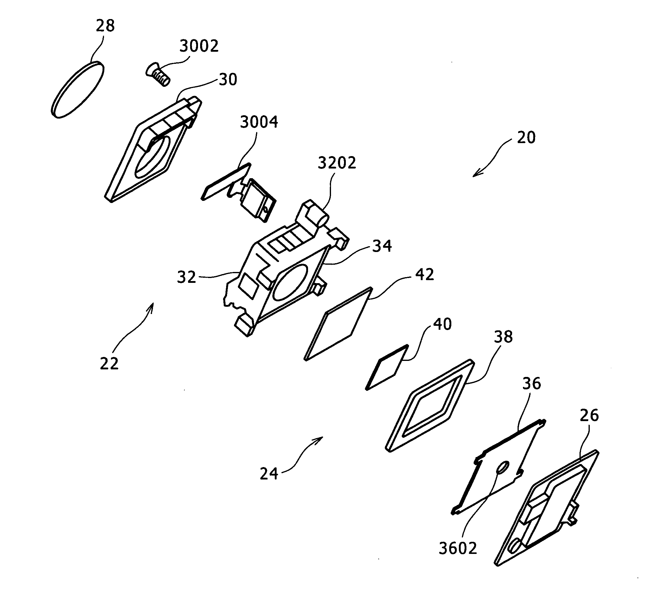
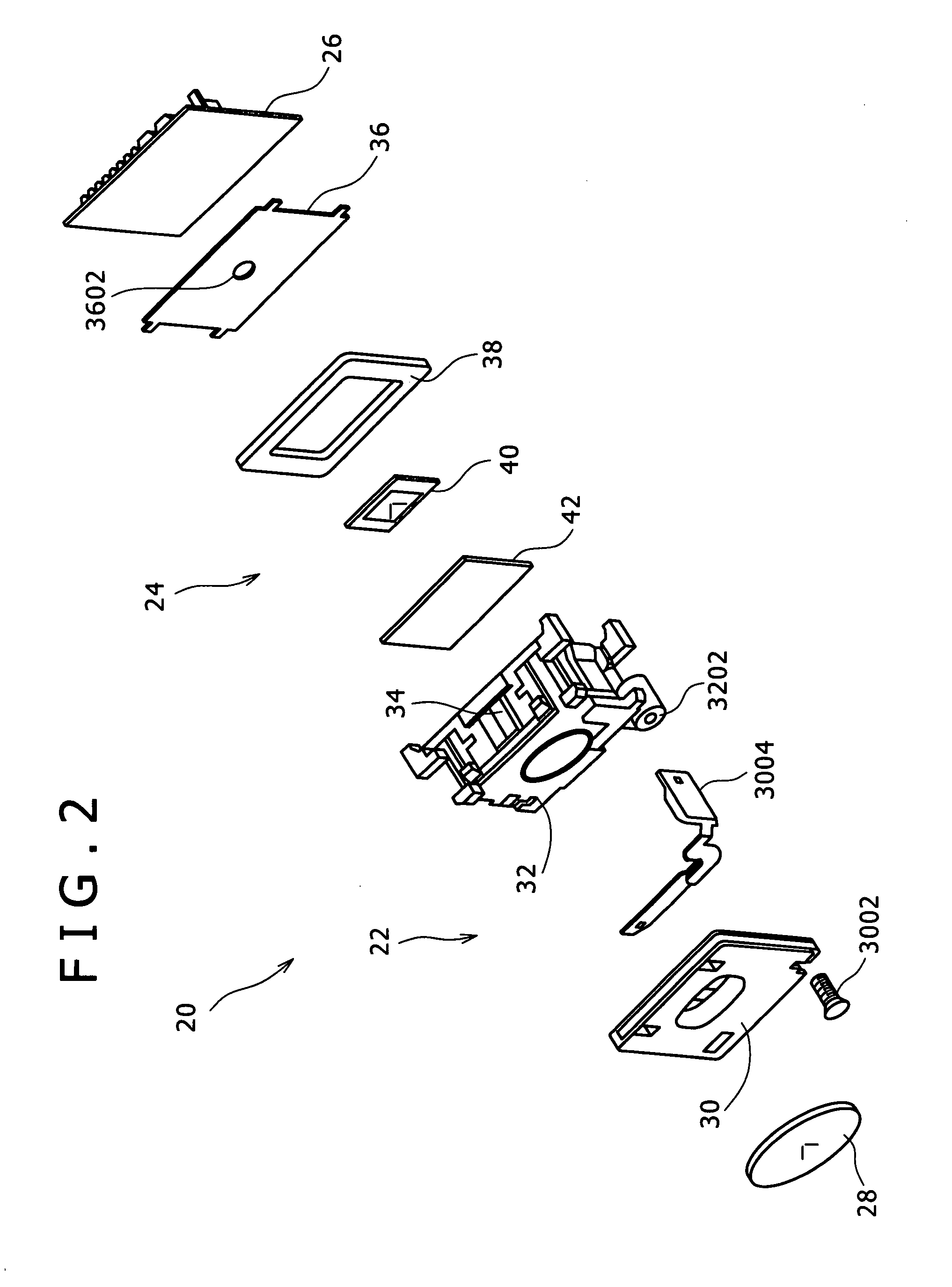
[0024]FIGS. 2 and 3 show the camera module 20 in an exploded perspective view, and FIG. 4 shows a cross sectional view of the camera...


PUM


Abstract

An image pickup apparatus may include a wiring board; a frame member having a framework-like shape and disposed on the wiring board, an image pickup element disposed on the inner side of the frame member on the wiring board, and a transparent cover disposed on the frame member. The wiring board and the frame member may be attached to each other by thermosetting adhesive. The frame member may be made of a material which has a coefficient of thermal expansion lower than that of the wiring board and has a rigidity higher than that of the wiring board.

Description

CROSS-REFERENCE TO RELATED APPLICATIONS [0001] This application claims priority from Japanese Patent Application No. JP 2006-025779 filed with the Japanese Patent Office on Feb. 2, 2006, the entire content of which is incorporated herein by reference. BACKGROUND OF THE INVENTION [0002] This invention relates to an image pickup apparatus, a camera module, an electronic device, and a fabrication method for an image pickup apparatus. [0003] In recent years, electronic device in which an image pickup apparatus is incorporated such as portable telephone sets and PDAs (Personal Digital Assistants) have been provided. [0004] An image pickup apparatus for use with such electronic device is disclosed, for example, in Japanese Patent Laid-open No. 2005-101306 (hereinafter referred to as Patent Document 1). The image pickup apparatus disclosed in Patent Document 1 includes a wiring board, and a frame member having a framework-like shape and disposed on the wiring board. The image pickup appara...

Claims


Application Information

Patent Timeline
Patent Type & Authority Applications(United States)
IPC IPC(8): H01L33/00H01L27/14H04N25/00
CPCH01L27/14618H01L2224/48091H01L2224/73265H01L2924/00011H01L2924/00014H01L2224/45147H01L2924/00H01L2924/01005H04M1/027
Inventor NOMURA, TAKUMISHIBUYA, HITOSHI
Owner SONY CORP
Learn More