Wide-Angle Lens, Optical Device Using the Wide-Angle Lens, and Method for Fabricating the Wide-Angle Lens

a wide-angle lens and optical device technology, applied in optics, instruments, electrical devices, etc., can solve the problems of insufficient efforts to eliminate image distortion and difficulty in grasping the actual situation from the captured image, so as to reduce image distortion, reduce image distortion, and reduce image distortion

Inactive Publication Date: 2009-09-10
ROHM CO LTD
View PDF7 Cites 16 Cited by
  • Summary
  • Abstract
  • Description
  • Claims
  • Application Information

AI Technical Summary

Benefits of technology

[0008]It is, therefore, an object of the present invention to provide a wide-angle lens with reduced image distortion. Another object of the present invention to provide an optical device using such a wide-angle lens. Still another object of the present invention to provide a method for easily manufacturing such a wide-angle lens.
[0010]In a preferred embodiment, the image-forming side lens group is designed to be capable of forming an image of an object on an image-forming surface by itself with reduced image distortion.
[0019]According to a fifth aspect of the present invention, there is provided a method for manufacturing a wide-angle lens comprising an object-side lens group, an image-forming side lens group, and at least one converging lens arranged between the object-side lens group and the image-forming side lens group. The object-side lens group comprises at least one concave lens including a convex light incident surface on the object side. The light incident surface of the concave lens comprises a convex aspheric surface. The concave lens further includes a light emitting surface which is a substantially concave spherical surface. The method comprises the steps of preparing the image-forming side lens group to be capable of forming an image of an object on an image-forming surface by itself with reduced image distortion, and determining specifications of the lens for constituting the object-side lens group and the converging lens so that an image with reduced image distortion is to be formed on the image-forming surface.
[0020]According to a sixth aspect of the present invention, there is provided a method for manufacturing a wide-angle lens comprising an object-side lens group; an image-forming side lens group, and at least one converging lens arranged between the object-side lens group and the image-forming side lens group. The object-side lens group comprises one or a plurality of concave lenses each including a light incident surface which is a convex aspheric surface and a light emitting surface which is a substantially concave spherical surface. The method is capable of producing wide-angle lenses of different angles of view by appropriately selecting the number of the concave lenses for constituting the object-side lens group. The method comprises preparing the image-forming side lens group by using a lens group of predetermined specifications which make it possible to form an image of an object on an image-forming surface by itself with reduced image distortion. In this method, when the object-side lens group is to consist of a single concave lens, specifications of the single concave lens and the converging lens are so determined that an image with reduced image distortion is to be formed on the image-forming surface. When the object-side lens group is to consist of two or more concave lenses, the specifications of the single concave lens for the structure in which the object-side lens group consists of a single concave lens is used as it is, and one or more additional concave lenses are arranged on the object side of the concave lens, and specifications of the additional concave lens or lenses and the converging lens are so determined that an image with reduced image distortion is to be formed on the image-forming surface.

Problems solved by technology

However, sufficient efforts have not been made to eliminate image distortion.
However, due to the large image distortion caused by the wide angle of view, it is difficult to grasp the actual situation from the captured image.

Method used


Image

  • Wide-Angle Lens, Optical Device Using the Wide-Angle Lens, and Method for Fabricating the Wide-Angle Lens
  • Wide-Angle Lens, Optical Device Using the Wide-Angle Lens, and Method for Fabricating the Wide-Angle Lens
  • Wide-Angle Lens, Optical Device Using the Wide-Angle Lens, and Method for Fabricating the Wide-Angle Lens

Examples


first embodiment

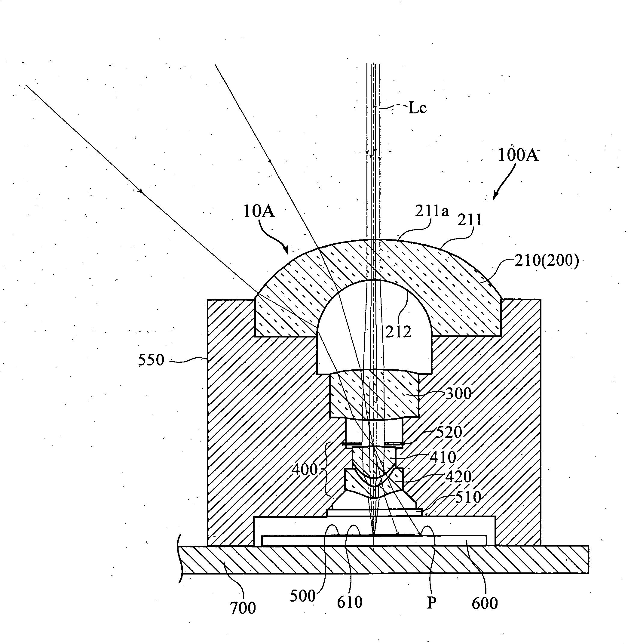
[0028]FIG. 1 shows the overall structure of a camera module 100A incorporating a wide-angle lens 10A according to the present invention.

[0029]The wide-angle lens 10A includes an object-side lens 200 comprising a concave lens 210, an image-forming side lens group 400 comprising a plurality of lenses 410 and 420, and a converging lens 300 arranged between the object-side concave lens 210 and the image-forming side lens group 400. The lenses 210, 300, 410 and 420 are arranged along a common central axis Lc and held by a lens holder 550. A two-dimensional area sensor 600, which may be a CCD sensor, is so arranged that its light receiving surface 610 is located on an image-forming surface 500. The two-dimensional area sensor 600 is mounted on a substrate 700. The lens holder 550 is also mounted on the substrate 700 to define the positional relationship among the lenses 210, 300, 410, 420 and the positional relationship between each of the lenses 210, 300, 410, 420 and the image-forming s...

second embodiment

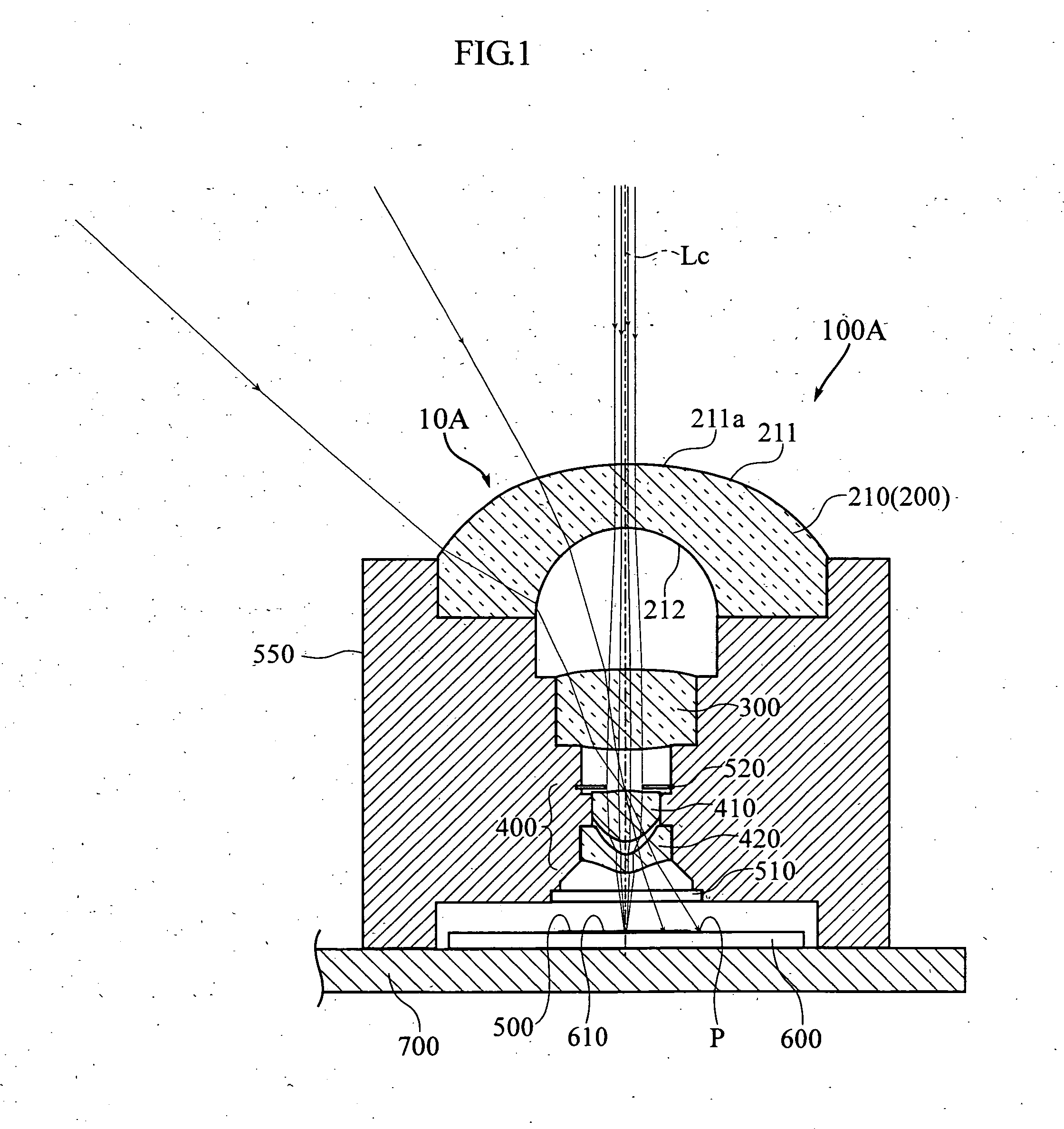
[0038]FIG. 2 shows the overall structure of a camera module 100B incorporating a wide-angle lens 10B according to the present invention.

[0039]The wide-angle lens 10B of the second embodiment differs from the wide-angle lens 10A of the first embodiment shown in FIG. 1 in that the wide-angle lens 10B includes two concave lenses 210 and 220 which constitute an object-side lens group 200. The wide-angle lens 10B of the second embodiment is the same as that of the first embodiment in that it includes an image-forming side lens group 400, a converging lens 300 is arranged between the object-side lens group 200 and the image-forming side lens group 400, the lenses 210, 220, 300, 410, 420 are supported by a lens holder 550 mounted on a substrate 700, a diaphragm 520 and an infrared light filter 510 are arranged at predetermined positions, and a light receiving surface 610 of a two-dimensional area sensor 600 mounted on the substrate 700 is arranged on an image-forming surface 500.

[0040]Of t...

third embodiment

[0045]FIG. 3 shows the overall structure of a camera module 100C incorporating a wide-angle lens 10C according to the present invention.

[0046]The wide-angle lens 10C of the second embodiment differs from the wide-angle lens 10A of the first embodiment shown in FIG. 1 in that the wide-angle lens 10C includes three concave lenses 210, 220 and 230 which constitute an object-side lens group 200. The wide-angle lens 10C of the third embodiment is the same as that of the first embodiment shown in FIG. 1 in that it includes an image-forming side lens group 400, a converging lens 300 is arranged between the object-side lens group 200 and the image-forming side lens group 400, the lenses 210, 220, 230, 300, 410, 420 are supported by a lens holder 550 mounted on a substrate 700, a diaphragm 520 and an infrared light filter 510 are arranged at predetermined positions, and a light receiving surface 610 of a two-dimensional area sensor 600 mounted on the substrate 700 is arranged on an image-for...


PUM


Abstract

A wide-angle lens includes an object-side lens group 200, an image-forming side lens group 400, and at least one converging lens 300 arranged between the object-side lens group 200 and the image-forming side lens group 400. The object-side lens group 200 includes at least one concave lens 210 including a convex light incident surface 211 on the object side. The light incident surface 211 of the concave lens 210 is a convex aspheric surface 211a whose curvature increases from a portion adjacent to the central optical axis toward the periphery of the lens. The concave lens further includes a light emitting surface 212 which is a substantially concave spherical surface.

Description

TECHNICAL FIELD[0001]The present invention relates to a wide-angle lens, an optical device using a wide-angle lens, and a method for manufacturing a wide-angle lens.BACKGROUND ART[0002]A lens whose angle of view is not smaller than 60° is called a wide-angle lens, and a lens whose angle of view is not smaller than 100° is called a super-wide-angle lens. An example of super-wide-angle lens is disclosed in Patent Document 1.[0003]The super-wide-angle lens disclosed in Patent Document 1 includes a concave lens unit arranged on an object side and a converging lens unit arranged on an image-forming side. The concave lens unit comprises a concave lens group made up of a plurality of concave lenses. Generally, the angle of view of the wide-angle lens increases as the number of the concave lenses constituting the concave lens group increases. Further, to achieve a wide angle of view, as the concave lenses for constituting the concave lens group, use is made of a lens having a light incident...

Claims


Application Information

Patent Timeline
Patent Type & Authority Applications(United States)
IPC IPC(8): G02B13/14G02B13/18G02B13/00
CPCG02B13/04G02B13/06H04N1/19594H04N1/10H04N1/195H04N1/02805
Inventor FUJIMOTO, HISAYOSHI
Owner ROHM CO LTD
Why Eureka
Try Eureka