Method and System for OFDM Symbol Timing Synchronization

a symbol timing and symbol timing technology, applied in the field of communication systems, can solve the problems of unrecoverable distortion, distorted transmission, and often significant performance degradation of time domain methods, and achieve the effect of low complexity and high performan

Inactive Publication Date: 2005-03-24
ITE TECH INC
View PDF5 Cites 37 Cited by
  • Summary
  • Abstract
  • Description
  • Claims
  • Application Information

AI Technical Summary

Benefits of technology

The invention is a system for synchronizing the timing of signals in the frequency domain using a method called orthogonal frequency division multiplexing (OFDM). The system is designed to be simple and effective. It converts a received signal to a different frequency range and calculates the phase angles of the signal's tones. It then calculates the difference between the phase angles of two consecutive gaps in the signal. By estimating this difference, the system can accurately synchronize the timing of the signal's symbols. This invention is useful for a wide range of applications that require precise timing in the frequency domain.

Problems solved by technology

The patent text discusses the problem of distortion in communication systems caused by inter-symbol interference (ISI). ISI occurs when the waveforms of contiguous OFDM symbols interfere with each other, leading to unrecoverable distortion. To mitigate the effect of ISI, some systems use a so-called circular prefix or suffix to act as guardian intervals between contiguous OFDM symbols. However, it is crucial to properly determine the start and end of each individual OFDM symbol and then compensate any timing offset, which is called symbol timing synchronization. The patent text describes a frequency domain method with low complexity for OFDM symbol timing offset estimation. The technical problem addressed in this patent text is how to accurately and efficiently synchronize the timing of OFDM symbols in a communication system, despite the presence of strong narrowband interference or Gaussian noise.

Method used


Image

  • Method and System for OFDM Symbol Timing Synchronization
  • Method and System for OFDM Symbol Timing Synchronization
  • Method and System for OFDM Symbol Timing Synchronization

Examples


Embodiment Construction

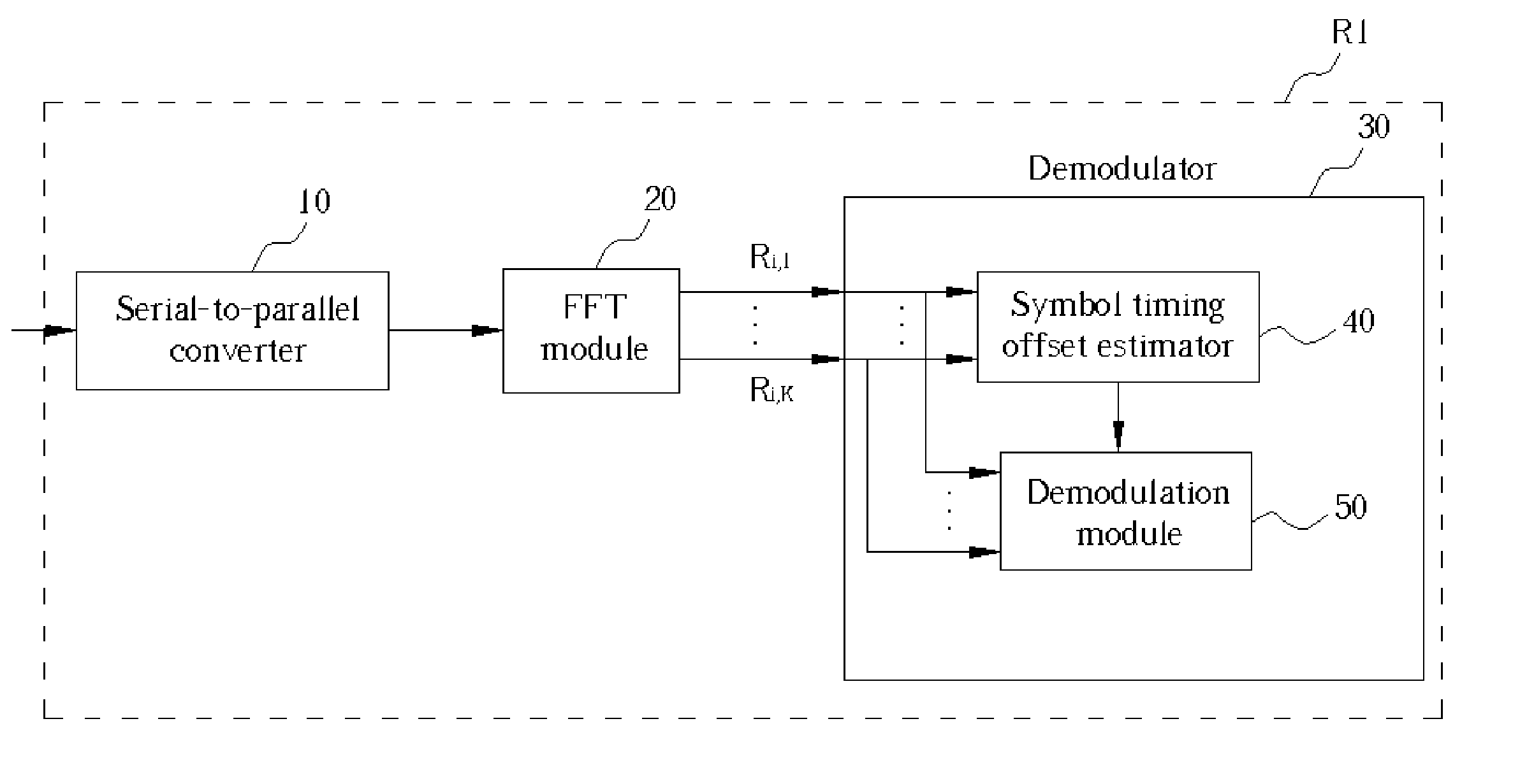
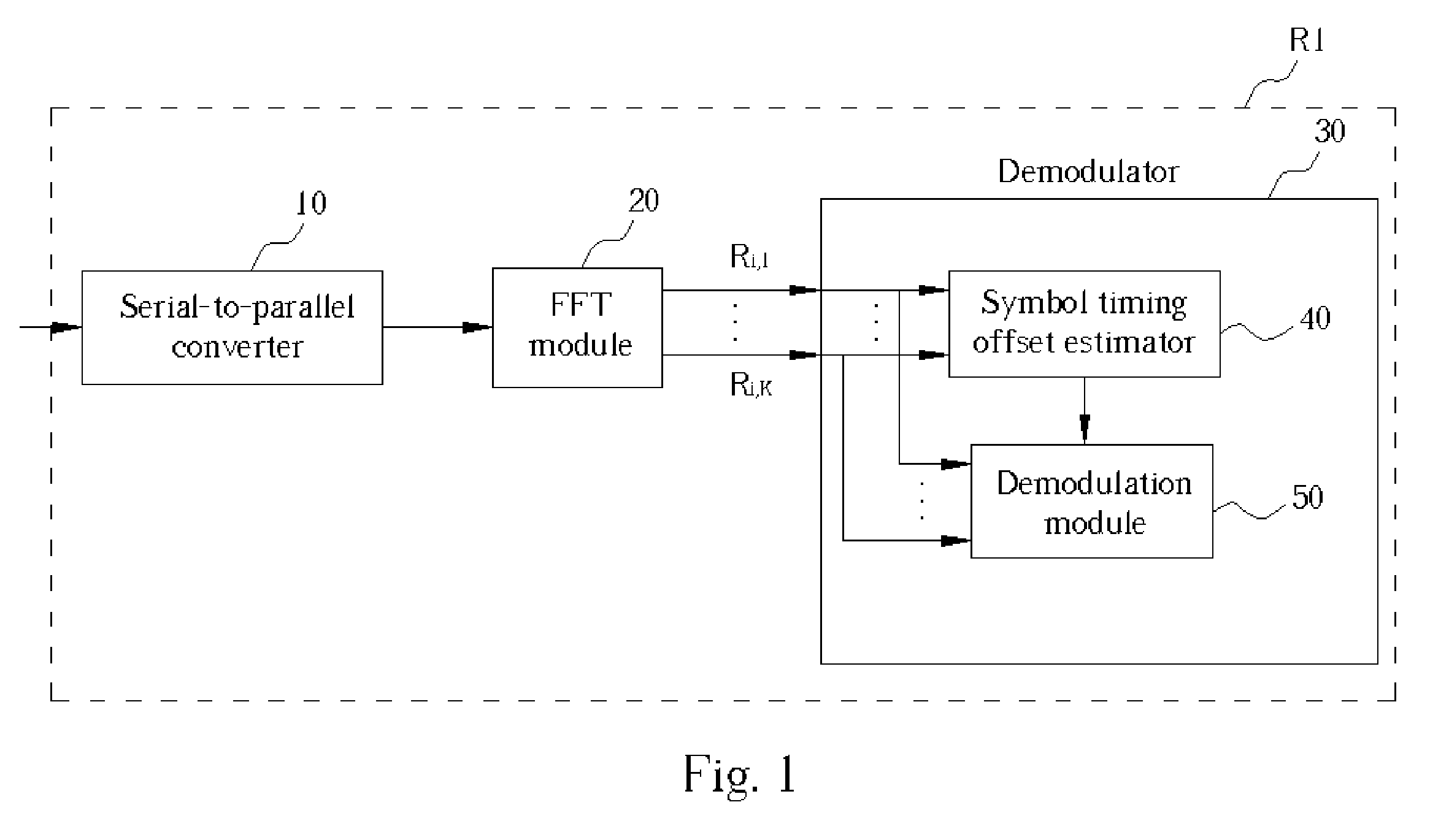
Please refer to FIG. 1. FIG. 1 is a block diagram of an OFDM / DMT receiver R1 according to the present invention. A serial-to-parallel converter 10 is capable of performing serial-to-parallel conversion on input time domain digital signals. A fast Fourier transform (FFT) module 20 is electrically connected to the serial-to-parallel converter 10 and transforms the time domain digital signals to obtain a frequency spectrum for demodulation. A demodulator 30 is electrically connected to the FFT module 20 to perform the demodulation. The demodulator 30 comprises a demodulation module 50 for demodulating the frequency domain digital signal and a symbol timing offset estimator 40 electrically connected to the FFT module 20. Complex output of the FFT is denoted as Ri,k for the kth tone of the ith received symbol. Ri,k can be modeled as a weighted version of the transmitted symbol corrupted by additive noise. If the cyclic prefix / suffix is inserted in between contiguous OFDM symbols, then t...


PUM


Abstract

A method includes converting a received time domain digital signal to a corresponding frequency domain digital signal, calculating phase angles of tones of at least one symbol of the frequency domain digital signal when a symbol timing offset exists, and calculating at least one differential phase offset (DPO). A DPO is the difference between two consecutive gaps, a gap being the difference between the phase angle of a tone of the symbol of the frequency domain digital signal when the timing offset of the symbol exists and a correct phase angle of the tone of the symbol of the frequency domain digital signal. The method estimates the symbol timing offset with at least one DPO.

Description


Claims


Application Information

Patent Timeline
Owner ITE TECH INC
Why Eureka
Try Eureka