Modular receptacle assembly and interface with integral optical indication

a technology of module receptacle and optical indication, which is applied in the direction of coupling device connection, instruments, mechanical equipment, etc., can solve the problems of affecting the signal flow between the plugs, and affecting the operation of the plug and the socket. , the approach also has drawbacks, and the cost of the project is high

Active Publication Date: 2005-03-24
EXTREME NETWORKS INC
View PDF11 Cites 78 Cited by
  • Summary
  • Abstract
  • Description
  • Claims
  • Application Information

AI Technical Summary

Benefits of technology

[0015] Another aspect of the invention is a method of providing status indication for a multi-receptacle modular RJ-45 receptacle assembly. The method includes providing a plurality of modular plugs having leading and trailing portions fabricated from an optically transmissive material, and providing a plurality stacked receptacles having wall portions extending from a front plane to an end wall, the receptacles each sized and shaped to releasably receive the leading portion of a modular plug therein. The method also includes utilizing a plurality of light pipes each having a proximal end and a distal end, coupling at least one of the proximal ends to each receptacle, extending the distal ends to a light source, and maintaining the light pipes free of the front plane. Additional aspects of this method include locating each proximal end to radiate light onto the leading portion of a plug disposed therein, and using an actuator to selectively operate the light pipes, wherein light is selectively transmitted from the leading portion to the trailing portion, so that the trailing portion serves as an integral optical indicator.

Problems solved by technology

A drawback associated with face plane-mounted LEDs is that the electrical leads supplying power to them tend to generate electromagnetic (EM) noise that without compensation, may disrupt the signals flowing between the plugs 26 and receptacles 12.
This approach, however, also has drawbacks.
Concomitantly, it may be difficult and potentially expensive from a manufacturability standpoint, to provide sufficient clearance to extend the light pipes 20 all the way from a light source (e.g., LED 22) to the face plane 16 without binding or otherwise interfering with proper insertion / withdrawal of plug 26.
However, such back side receptacle lighting tends to become increasingly cumbersome and expensive as the density of receptacles increases, such as in devices that employ multiple stacked rows of receptacles.

Method used


Image

  • Modular receptacle assembly and interface with integral optical indication
  • Modular receptacle assembly and interface with integral optical indication
  • Modular receptacle assembly and interface with integral optical indication

Examples


Embodiment Construction

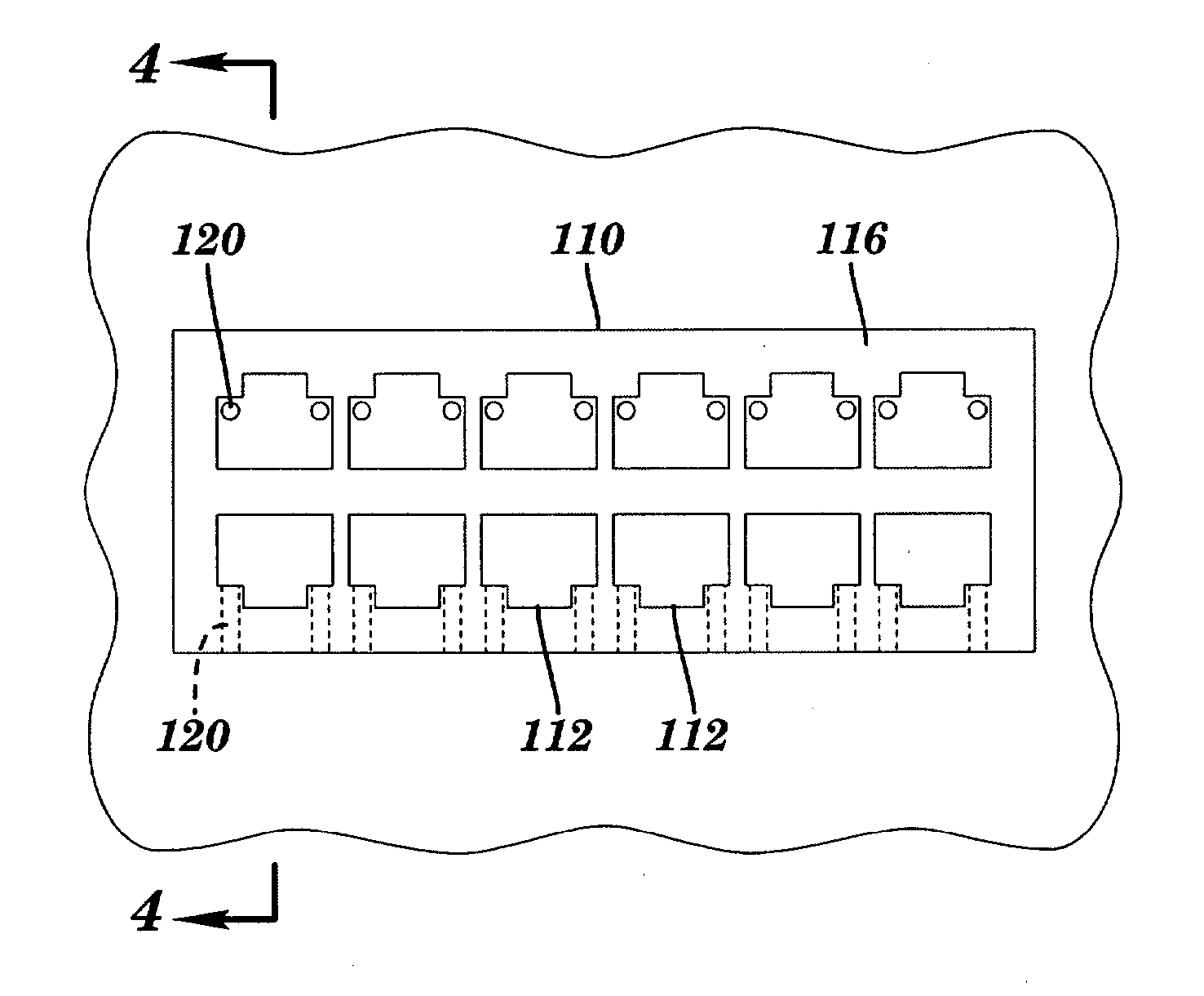
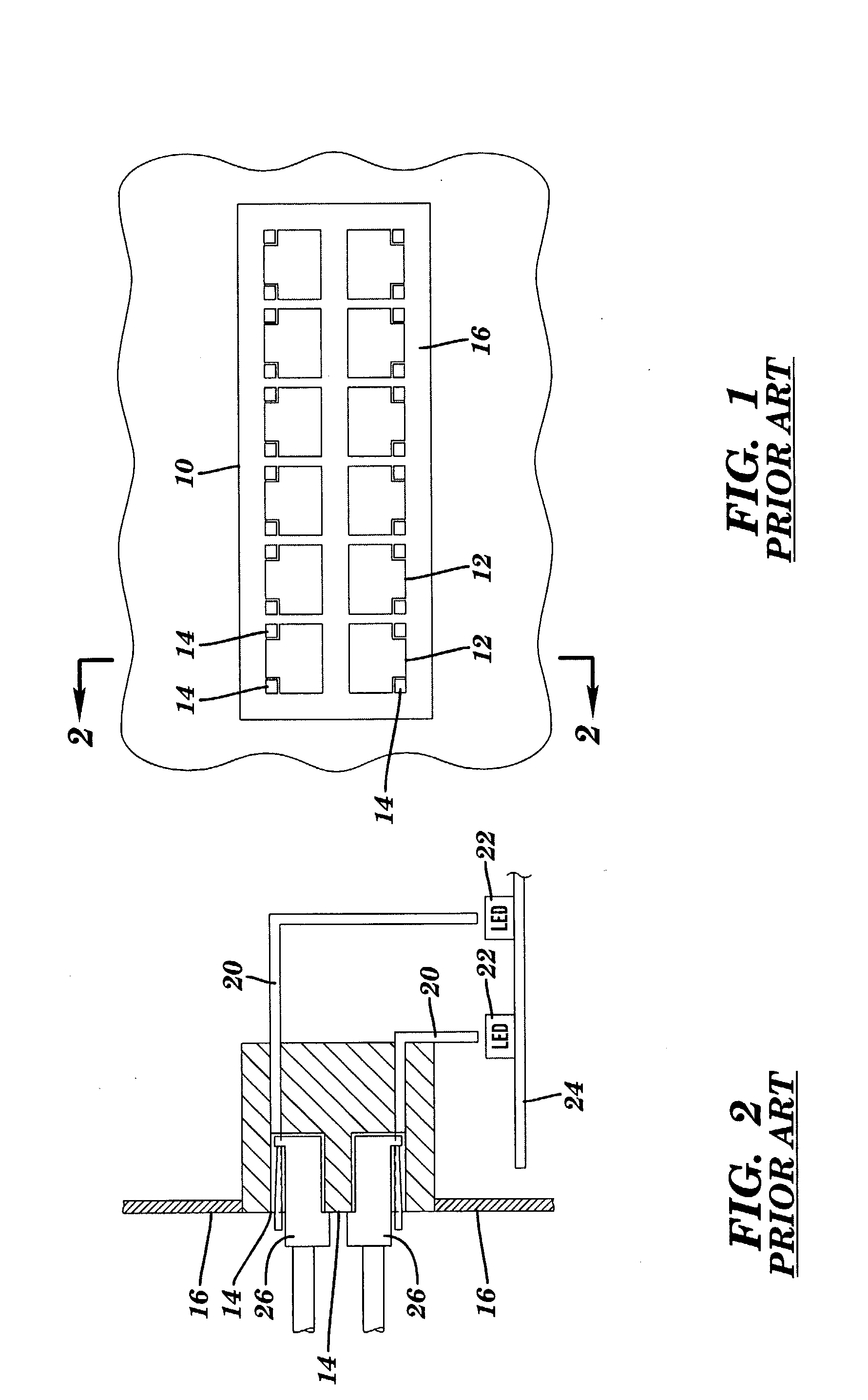
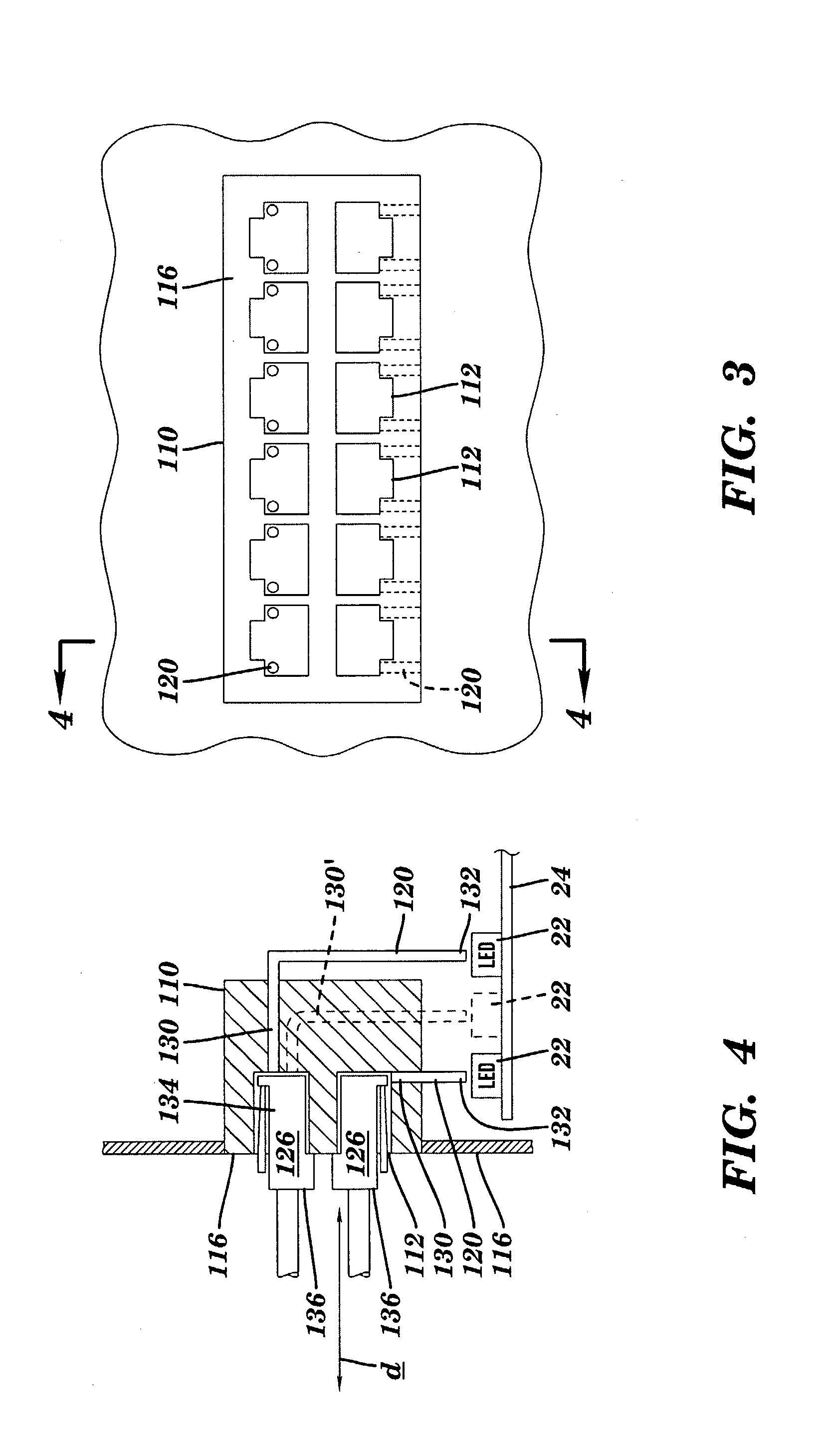
[0031] In the following detailed description, reference is made to the accompanying drawings that form a part hereof, and in which is shown by way of illustration, specific embodiments in which the invention may be practiced. These embodiments are described in sufficient detail to enable those skilled in the art to practice the invention, and it is to be understood that other embodiments may be utilized. It is also to be understood that structural, procedural and system changes may be made without departing from the spirit and scope of the present invention. The following detailed description is, therefore, not to be taken in a limiting sense, and the scope of the present invention is defined by the appended claims and their equivalents. For clarity of exposition, like features shown in the accompanying drawings shall be indicated with like reference numerals and similar features as shown in alternate embodiments in the drawings shall be indicated with similar reference numerals.

[0...


PUM


Abstract

A modular receptacle assembly includes integral optical indication. The receptacle assembly includes a module housing one or more receptacles configured to releasably receive, in an insertion direction, a leading portion of a modular plug. A light pipe having proximal and distal ends, is disposed in the footprint of the module. The proximal end is coupled to the receptacle, and the distal end is coupled to a light source. The proximal end is configured to radiate light onto the leading portion of a plug disposed within said receptacle. An actuator is configured to selectively operate the light pipe.

Description

RELATED APPLICATION [0001] This application claims the benefit of U.S. Provisional Application Ser. No. 60 / 504,493, entitled MODULAR RECEPTACLE AND INTERFACE WITH INTEGRAL OPTICAL INDICATION, filed Sep. 19, 2003.BACKGROUND [0002] 1. Technical Field [0003] This invention relates to modular connectors, and more particularly to modular plug and socket connectors having integral optical displays for convenient status indication. [0004] 2. Background Information [0005] Conventional double row, multiple receptacle RJ-45 (CAT 5) receptacle assemblies 10, such as shown in FIG. 1, are well-known. This particular example includes two stacked rows of six receptacles 12. A pair of optical indicators 14 are disposed in the face plane 16 of the receptacle assembly, proximate each receptacle 12. Optical indicators 14 are typically used for status indication. [0006] Such location of indicators 14 proximate receptacles 12 was intended to improve upon earlier approaches in which status indicators wer...

Claims


Application Information

Patent Timeline
Patent Type & Authority Applications(United States)
IPC IPC(8): F21V8/00G02B6/42G02B6/43H01R13/66H01R13/717
CPCG02B6/0001G02B6/421G02B6/4249G02B6/4292H01R24/62H01R13/6691H01R13/717H01R13/7172H01R13/6641
Inventor THORNTON, MARTIN Q.GRAHAM, RICHARD W.STEWART, THOMAS A.FERLAND, WILLIAM M.
Owner EXTREME NETWORKS INC
Why Eureka
Try Eureka