Fusing apparatus for an image forming apparatus and a method thereof

a technology of fusing apparatus and fusing nip, which is applied in the direction of electrographic process apparatus, instruments, optics, etc., can solve the problems of inconvenient use, printing paper often crumples, and the fusing apparatus cannot adapt to the various changes of the fusing nip, etc., to achieve the effect of improving the structur

Inactive Publication Date: 2005-03-24
SAMSUNG ELECTRONICS CO LTD
View PDF4 Cites 7 Cited by
  • Summary
  • Abstract
  • Description
  • Claims
  • Application Information

AI Technical Summary

Benefits of technology

The present invention has been made to overcome the above-mentioned problems of the prior art. Accordingly, it is an aspect of the present invention to provide a fusing apparatus and method for an image forming apparatus, which has an improved structure so that a fusing nip between rollers can be maintained regularly.

Problems solved by technology

Therefore, it is inconvenient to use since papers of various thickness cannot be accommodated.
However, because the conventional fusing apparatus has only two modes for the fusing nip, the fusing apparatus can not adaptively cope with the various changes of the fusing nip.
Further, when the pressure increases, the printing paper often crumples.
In contrast, when the pressure decreases, the fusing performance is deteriorated.

Method used


Image

  • Fusing apparatus for an image forming apparatus and a method thereof
  • Fusing apparatus for an image forming apparatus and a method thereof
  • Fusing apparatus for an image forming apparatus and a method thereof

Examples


Embodiment Construction

Embodiments of a fusing apparatus for an image forming apparatus according to embodiments of the present invention will now be described in detail with reference to the accompanying drawings.

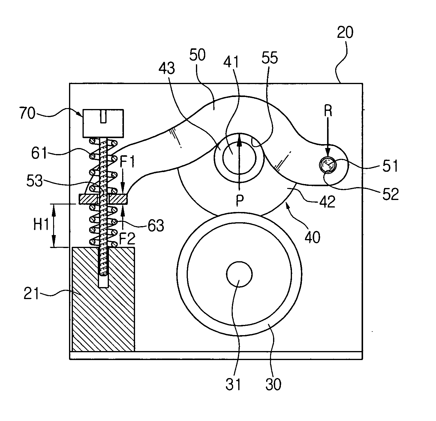
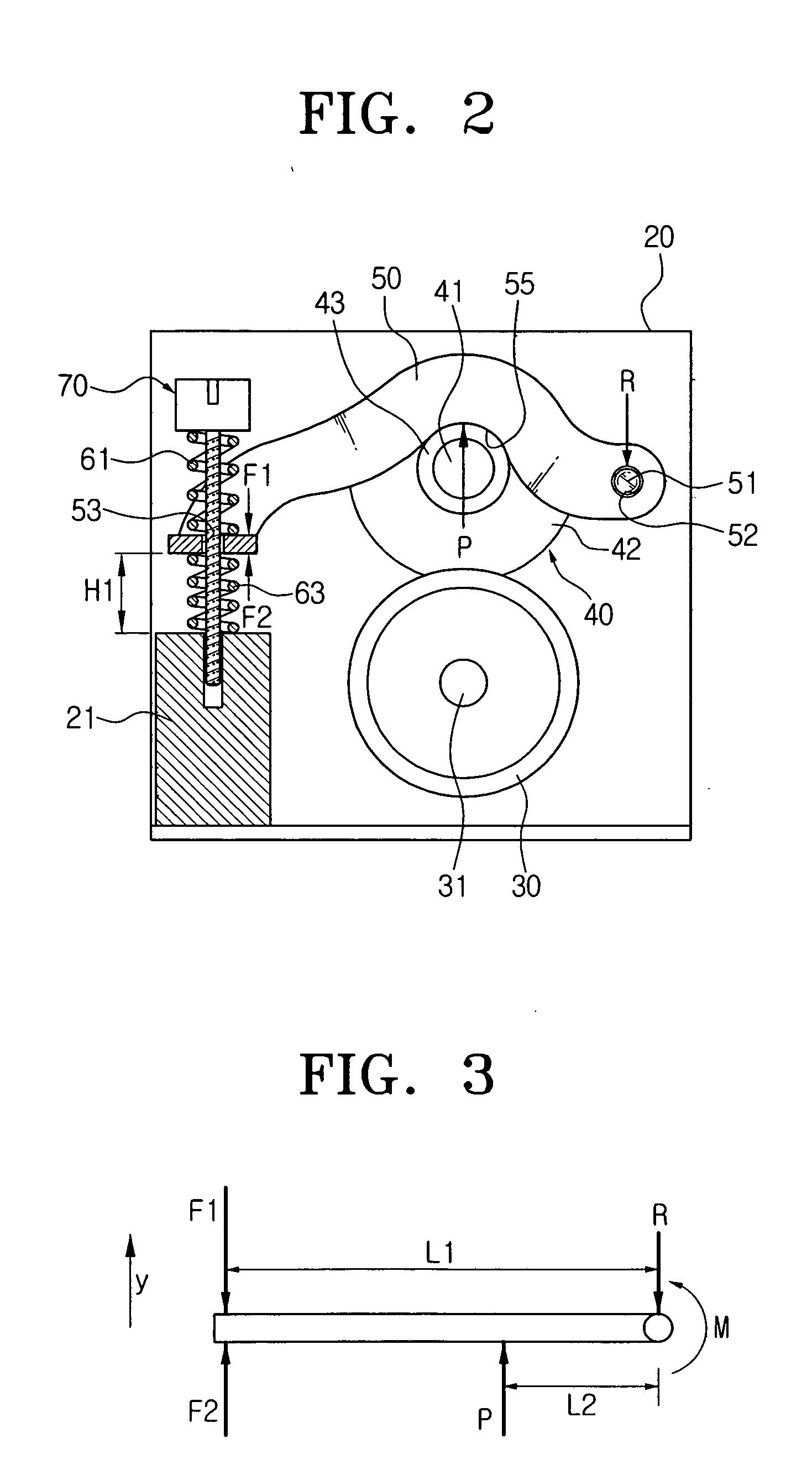
Referring to FIG. 2, a fusing apparatus of an image forming apparatus according to an embodiment of the present invention comprises a heating roller 30 rotatably mounted in a support frame 20, a pressing roller 40 rotating in contact with the heating roller 30, a hinge bracket 50 rotatably supporting the pressing roller 40, first and second elastic members 61 and 63 facing each other with the hinge bracket 50 interposed therebetween, and a guide member 70.

A heater 31 is mounted in the heating roller 30. The heating roller 30 rotates in contact with the pressing roller 40, fusing an image onto a printing paper passing between the rollers 30 and 40 using a predetermined heat and pressure.

The pressing roller 40 presses the heating roller 30 with a predetermined pressure, while rotating in co...


PUM


Abstract

A fusing apparatus and method for an image forming apparatus is disclosed. The apparatus and method comprise a heating roller rotatably mounted in a support frame, a pressing roller for rotating in contact with the heating roller, and defining a predetermined nip area by contact with the heating roller, a hinge bracket mounted in the support frame, and supporting either the pressing roller or the heating roller so that either roller rotates in contact with the other roller, first and second elastic members facing each other with the hinge bracket interposed therebetween, and elastically pushing the hinge bracket respectively, and a guide member for guiding movement of the hinge bracket while supporting the respective first and second elastic members, wherein the first and the second elastic members compress and expand reciprocally.

Description

CROSS-REFERENCE TO RELATED APPLICATIONS This application claims the benefit under 35 U.S.C. § 119(a) of Korean Application No. 2003-66169, filed Sep. 24, 2003, in the Korean Intellectual Property Office, the entire contents of which is incorporated herein by reference. BACKGROUND OF THE INVENTION 1. Field of the Invention The present invention relates to a fusing apparatus and method. More particularly, the present invention relates to a fusing apparatus and method for an image forming apparatus, which fuses a toner image into a printing paper with predetermined temperature and pressure. 2. Description of the Related Art A general electrophotography image forming apparatus such as a copier, and a laser printer uses an electrophotography developing method. In an electrophotography image forming apparatus, a photoconductive drum is electrified by an adjacent electrifying unit. A surface of the electrified photoconductive drum is exposed to a laser which is emitted from a laser sc...

Claims


Application Information

Patent Timeline
Patent Type & Authority Applications(United States)
IPC IPC(8): G03G15/20
CPCG03G15/2064G03G2215/2035
Inventor CHO, DURK-HYUNKIM, HWAN-GUEM
Owner SAMSUNG ELECTRONICS CO LTD
Why Eureka
Try Eureka