Substrate support

a technology of substrates and supports, applied in the direction of auxillary welding devices, charge manipulation, furnaces, etc., can solve the problems of significant substrate misalignment, high probability of damage, and difficult placement of glass substrates used for displays in load lock chambers

Inactive Publication Date: 2005-03-24
APPLIED MATERIALS INC
View PDF51 Cites 23 Cited by
  • Summary
  • Abstract
  • Description
  • Claims
  • Application Information

AI Technical Summary

Problems solved by technology

The positioning of glass substrates used for displays in a load lock chamber is difficult as compared to smaller, 200 mm and even 300 mm circular substrates.
For example, as glass substrates often have dimensions exceeding 550 mm by 650 mm, with trends towards 1.2 square meters and larger, small deviations in position may result in significant substrate misalignment.
A misaligned substrate has high probability of damage, resulting in a costly loss of the substrate.
Moreover, a misaligned substrate must be manually removed from the load lock chamber, thereby requiring costly loss of production time and diminished substrate throughput.
Thus, if the accuracy and repeatability of substrate placement by the user supplied robot is not within the designed specifications of the load lock chamber, substrate damage is likely.

Method used


Image

  • Substrate support
  • Substrate support
  • Substrate support

Examples


Embodiment Construction

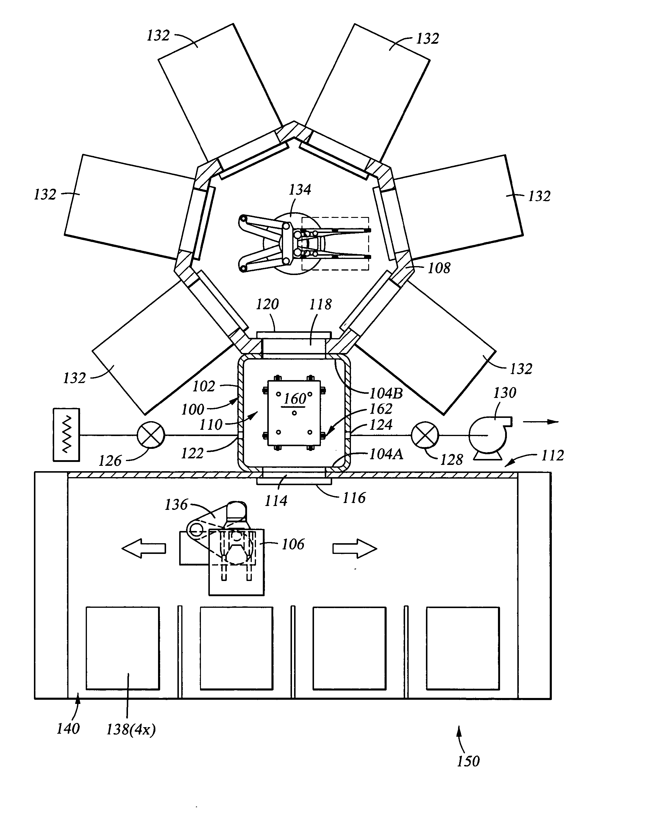
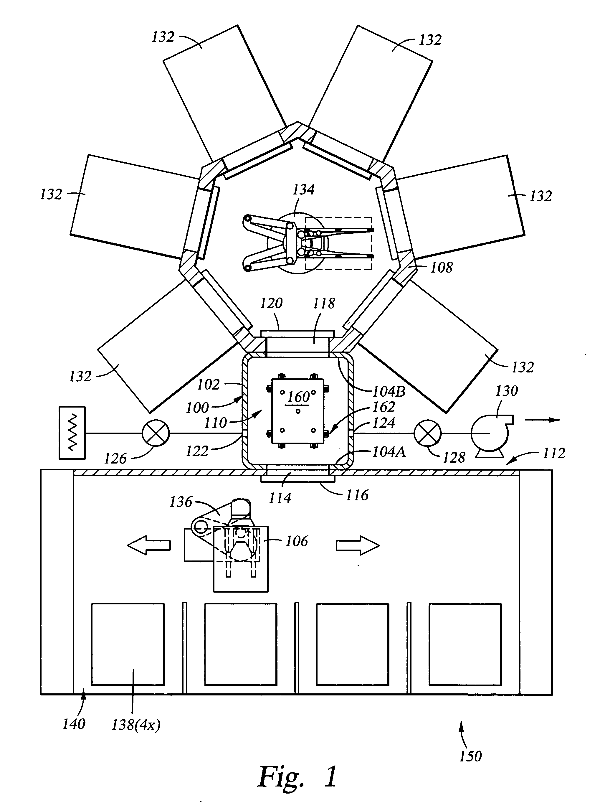
[0023] The invention generally provides a substrate support having an alignment mechanism that aligns or centers a substrate disposed thereon to a predetermined position. The invention is illustratively described below utilized in a dual substrate load lock chamber, such as those available from AKT, a division of Applied Materials, Inc., Santa Clara, Calif. However, it should be understood that the invention has utility in other configurations, for example, single substrate load lock chambers, multiple substrate load lock chambers, robot hand-off platforms, buffer stations and other devices utilized to support a substrate where the positional accuracy of the substrate is desired.

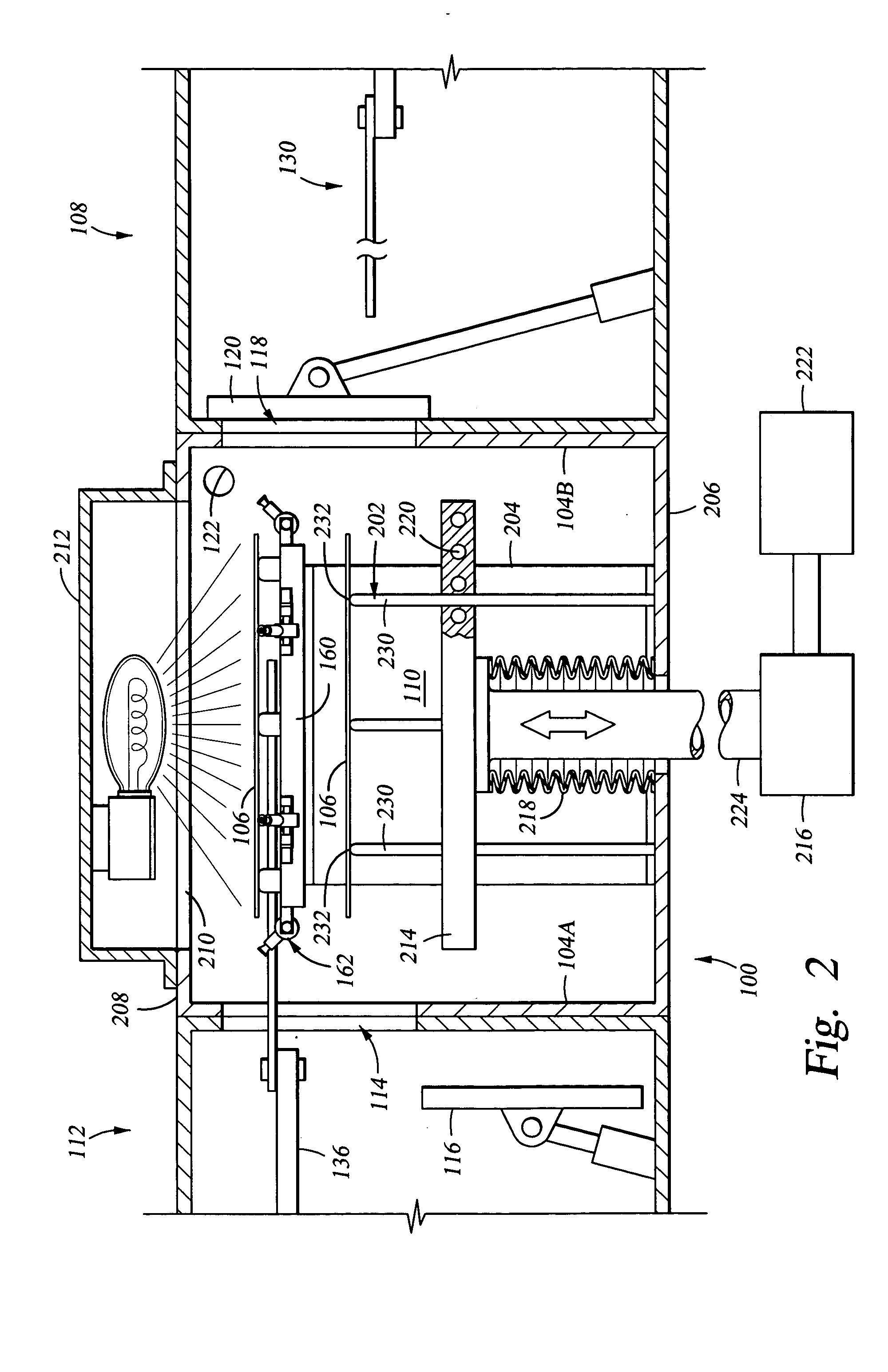
[0024]FIG. 1 is a cross sectional view of one embodiment of a process system 150. The process system 150 typically includes a transfer chamber 108 coupled to a factory interface 112 by a load lock chamber 100 that has at least one substrate alignment mechanism 162. The transfer chamber 108 has at least one ...


PUM

PropertyMeasurementUnit
axis of rotationaaaaaaaaaa
rotationaaaaaaaaaa
vacuum environmentaaaaaaaaaa

Abstract

A method and apparatus for supporting a substrate is generally provided. In one aspect, an apparatus for supporting a substrate includes a support plate having a first body disposed proximate thereto. A first pushing member is radially coupled to the first body and adapted to urge the substrate in a first direction parallel to the support plate when the first body rotates. In another aspect, a load lock chamber having a substrate support that supports a substrate placed thereon includes a cooling plate that is moved to actuate at least one alignment mechanism. The alignment mechanism includes a pushing member that urges the substrate in a first direction towards a center of the support. The pushing member may additionally rotate about an axis perpendicular to the first direction.

Description

CROSS-REFERENCE TO RELATED APPLICATIONS [0001] This application is a continuation application of co-pending U.S. patent application Ser. No. 10 / 084,762, filed Feb. 22, 2002, which is incorporated by reference herein.FIELD OF THE INVENTION [0002] Embodiments of the invention generally relate to a substrate support. BACKGROUND OF THE INVENTION [0003] Thin film transistors (TFTs) are conventionally made on large glass substrates or plates for use in monitors, flat panel displays, solar cells, personal digital assistants (PDAs), cell phones and the like. TFTs are made in a cluster tool by sequential deposition of various films including amorphous silicon, doped and undoped silicon oxides, silicon nitride and the like in a plurality of vacuum process chambers typically arranged around a central transfer chamber. The cluster tool is typically coupled to a factory interface that includes a plurality of substrate storage cassette that holds substrates before and after processing. A load loc...

Claims


Application Information

Patent Timeline
Patent Type & Authority Applications(United States)
IPC IPC(8): B65G49/07H01L21/205H01L21/68H01L21/687
CPCH01L21/68H01L21/68728H01L21/68778Y10S414/139Y10S414/141Y10S414/136H01L21/68792H01L21/00
Inventor KURITA, SHINICHIBLONIGAN, WENDELL T.ANWAR, SUHAILKIYOTAKE, TOSHIONGUYEN, HUNG T.
Owner APPLIED MATERIALS INC
Why Eureka
Try Eureka