Golf club head having a bridge member

a golf club head and bridge member technology, applied in the field of golf club heads, can solve the problem of limited control of the trajectory of golf balls

Active Publication Date: 2005-03-24
KARSTEN MFG CORP
View PDF34 Cites 29 Cited by
  • Summary
  • Abstract
  • Description
  • Claims
  • Application Information

AI Technical Summary

Benefits of technology

[0004] One or more of the above-mentioned needs in the art are satisfied by the disclosed golf club head of the present invention. The cavity back golf club head of the present invention may include a bridge member where the center of gravity is located between the bridge member and the rear of t...

Problems solved by technology

The control of the trajectory of a golf ball is limited by t...

Method used


Image

  • Golf club head having a bridge member
  • Golf club head having a bridge member
  • Golf club head having a bridge member

Examples


Embodiment Construction

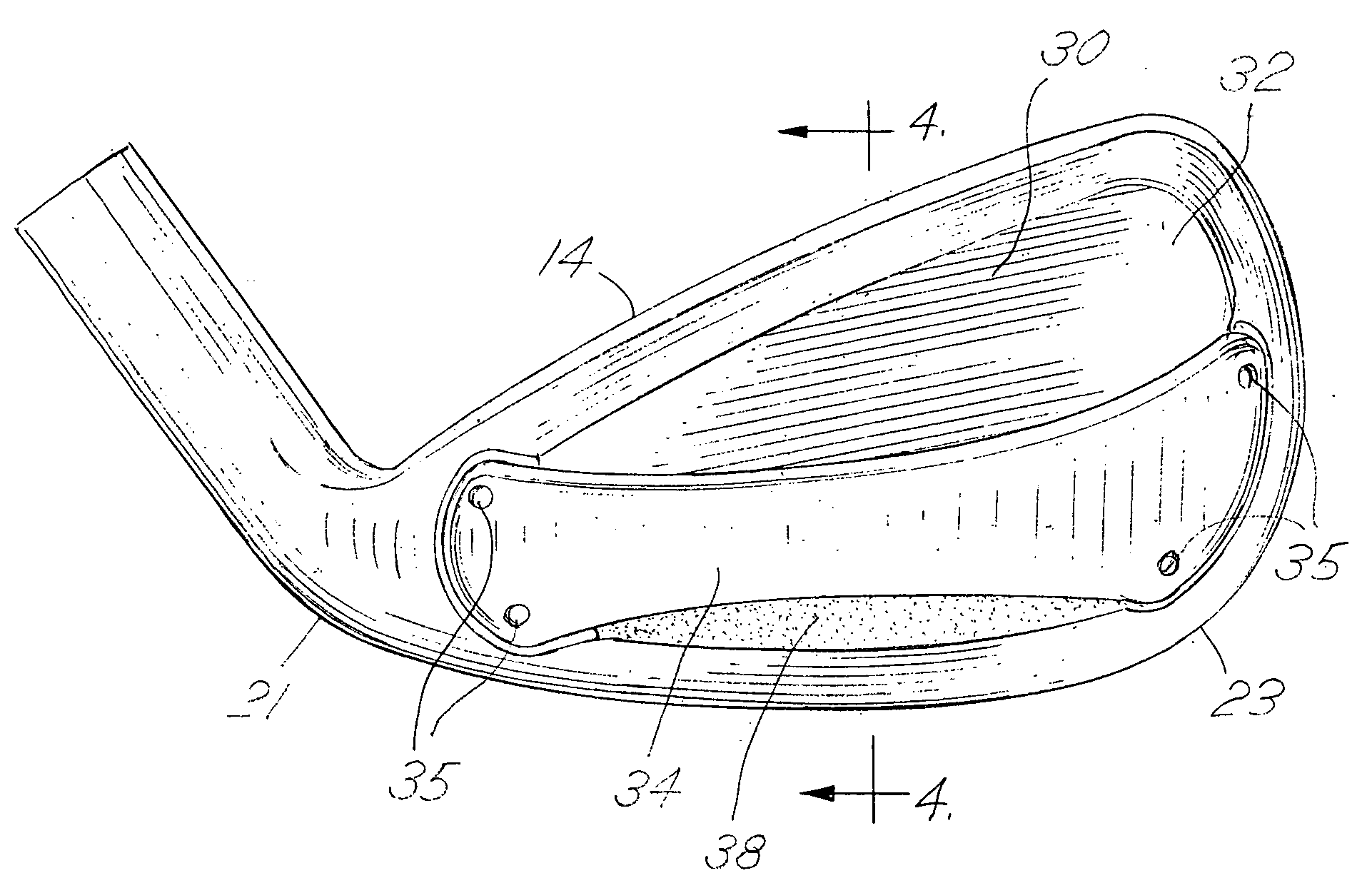
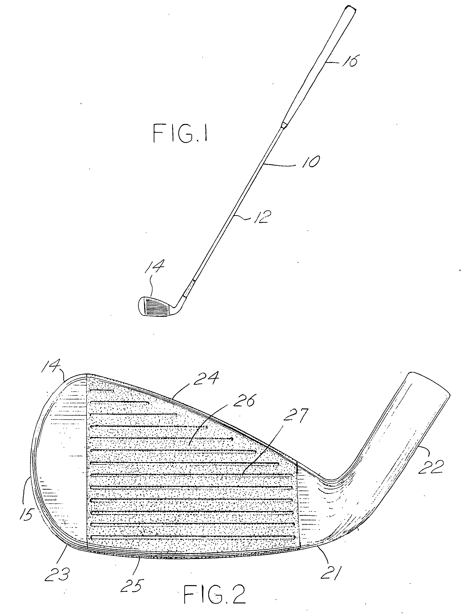
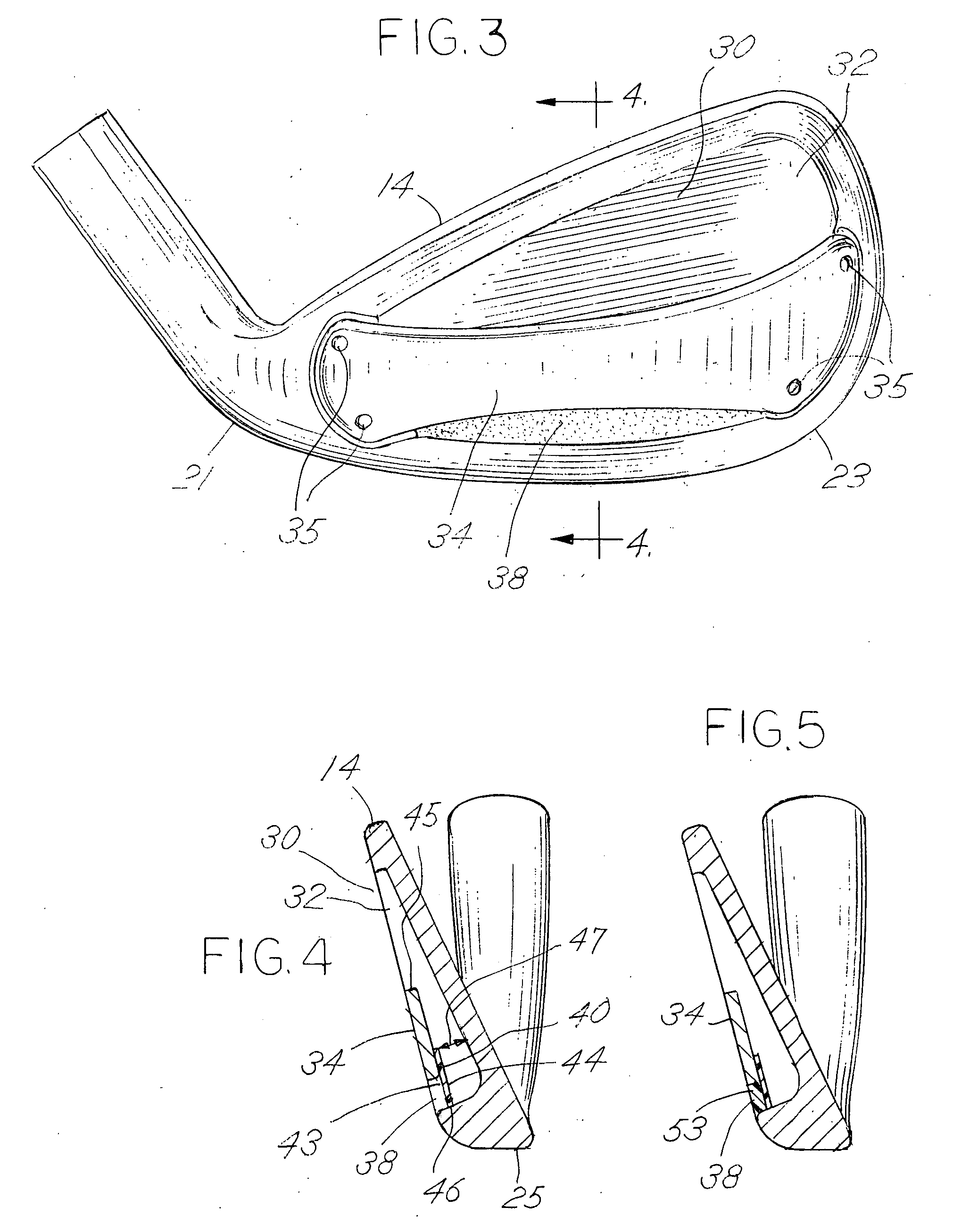
[0021] The following discussion and accompanying figures disclose various golf club heads in accordance with the present invention. For example, the golf club heads of the present invention can be utilized for the long iron clubs, two iron through five iron, and for the short iron clubs, six iron through pitching wedge. In the current description of the invention, FIGS. 1-5 are representative of the long iron clubs including the present invention, whereas, FIGS. 6-10 are representative of the short iron clubs including the present invention.

[0022] Referring to FIG. 1, golf club 10 includes a shaft 12 and a golf club head 14. The golf club head 14 of FIG. 1 may be representative of a two iron golf club head of the present invention. The shaft 12 of golf club 10 may be made of various materials such as steel, titanium, graphite, or a composite material. A grip 16 is positioned on the shaft 12 to provide a golfer with a slip resistant surface in which to grasp golf club 10.

[0023] As ...


PUM


Abstract

A cavity back golf club head having a bridge member is disclosed. The bridge member extends across a first rear cavity connecting a heel and a toe of the golf club head to control the trajectory of a golf ball. For the longer iron clubs, a wall extending from the sole portion of the cavity back golf club head to the bridge member defines a second cavity to further influence the trajectory of the golf ball. For the shorter iron clubs, the wall extends from the top portion of the cavity back golf club head to the bridge member.

Description

FIELD OF THE INVENTION [0001] The present invention relates to golf club heads. More particularly, the invention concerns cavity back golf club heads having a bridge member extending across a first rear cavity. The invention provides a second rear cavity connecting the bridge member to either the sole or top portion of the golf club head. BACKGROUND OF THE INVENTION [0002] Various golf club heads have been designed to improve a golfer's accuracy by assisting a golfer to square the club head face at impact with a golf ball. A number of these golf club heads reposition the weight of the golf club head in order to alter the location of the center of gravity. The location of the center of gravity of the golf club head is one factor that determines whether a golf ball is propelled in the intended direction. When the center of gravity is positioned behind the point of engagement on the contact surface, the golf ball follows a generally straight route. When the center of gravity is spaced ...

Claims


Application Information

Patent Timeline
IPC IPC(8): A63B53/04A63B59/00
CPCA63B53/04A63B53/047A63B59/0092A63B2053/045A63B2053/0416A63B2053/0491A63B2209/00A63B2053/005A63B60/54A63B53/005A63B53/045A63B53/0416A63B60/02A63B60/00
Inventor STITES, JOHN THOMASTAYLOR, MICHAEL G.FRANKLIN, DAVID N.SLAUGHTER, BYRON COLE
Owner KARSTEN MFG CORP
Why Eureka
Try Eureka