Method and article for evaluating and optimizing joined thermoplastic parts

a technology of thermoplastic parts and optimization methods, applied in the field of thermoplastic workpiece joining, can solve the problems of inconvenient testing of cylindrical articles with joints interrupting the circumference, and achieve the effect of convenient testing and much more economic and efficient selection

Inactive Publication Date: 2005-03-31
BASF AG
View PDF0 Cites 25 Cited by
  • Summary
  • Abstract
  • Description
  • Claims
  • Application Information

AI Technical Summary

Benefits of technology

[0016] The method of the invention is suited for optimizing articles composed of a wide variety of polymeric materials, including ABS (acrylonitrite / butadiene / styrene), ASA (acrylonitrite / styrene / acrylate), BS (styrene / butadiene block copolymer), MABS (methyl methacrylate / acrylonitrite / butadiene / styrene), Nylons 6, 66, 46, and 12 (polyamide), PSU (polysulfone), PE (polyethylene), PEX (cross-linked polyethylene), PP (polypropene), PES (polyethersulfone), POM (polyoxymethylene), PEK (polyether ketone), PEEK (polyether ether ketone), PS (polystyrene), PVC (polyvinyl chloride), PPS (polypropylene sulfide), and SAN (styrene / acrylonitrite copolymer). In some embodiments, the method of the invention advantageously allows optimization of the mechanical properties of articles comprising plural materials having some degree of chemical incompatibility.
[0017] The optimization methods provided by the present invention allow conditions used in welding and injection molding processes to be selected much more economically and efficiently as the result of using test samples that generally function as surrogates for test samples that would otherwise have to be machined from finished articles. The test samples incorporate joints or knit lines that result in mechanical properties that are similar to those that would be exhibited by samples taken from the finished articles that incorporate similarly joined regions wherein the interfaces are similarly shaped. Optimization of conditions such as heat, pressure, exposure to heating radiation, and other salient parameters characterizing welding and injection molding processes can be replicated in the formation of the test samples. As a result, the expense, inconvenience, and difficulty of carrying out trials that entail forming large-scale parts, which subsequently must be destructively tested, is virtually eliminated. In addition, many finished articles have a three-dimensional geometry such that their joints occur at positions that do not allow test samples with standard geometry to be fabricated. For example, cylindrical articles having joints interrupting the circumference are not conveniently tested, since there is no planar region that can be sectioned to provide standard planar test samples. By way of contrast, the processes used to construct such items may be readily optimized in accordance with the present method. Moreover, the ease of fabricating test samples in accordance with the present method allows a more thorough optimization, since more replicate testing and a wider range of experimental conditions may be explored at a feasible cost, compared to prior full-scale testing methods.

Problems solved by technology

In addition, many finished articles have a three-dimensional geometry such that their joints occur at positions that do not allow test samples with standard geometry to be fabricated.
For example, cylindrical articles having joints interrupting the circumference are not conveniently tested, since there is no planar region that can be sectioned to provide standard planar test samples.

Method used


Image

  • Method and article for evaluating and optimizing joined thermoplastic parts
  • Method and article for evaluating and optimizing joined thermoplastic parts
  • Method and article for evaluating and optimizing joined thermoplastic parts

Examples


Embodiment Construction

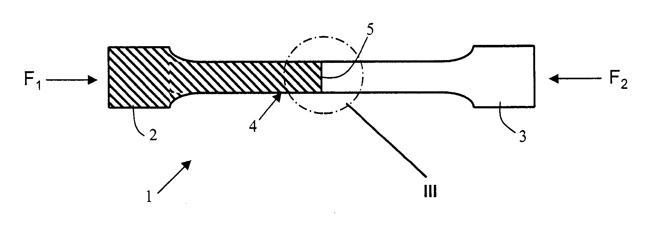
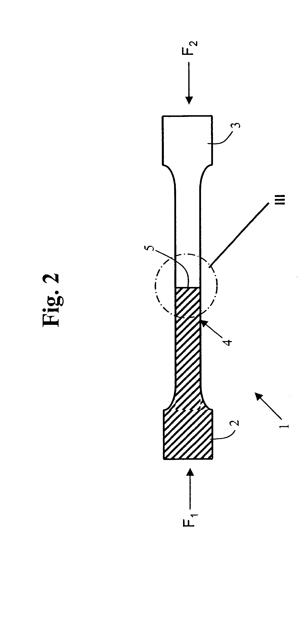
[0026] In one aspect, the present invention is directed to the optimization of mechanical properties of thermoplastic articles made by welding or injection molding. The optimization method of the present invention is preferably carried out using mechanical testing data obtained with test samples such as that depicted generally at 1 in FIG. 2. The geometry of the test samples, including their dimensions and shape, is normally chosen in accordance with recognized protocols established by entities such as the American Society for Testing of Materials (ASTM) and the International Standards Organization (ISO). Sample 1 includes end grip portions 2, 3 and an active gage portion 4 with an interface 5 and an inter-phase region substantially in the center of gage portion 4. Various shapes that interface 5 can assume are shown in the enlarged views of region III seen in FIGS. 3A-3G. The present test samples are generally planar, but may also be cylindrical for some applications.

[0027] Test s...


PUM

PropertyMeasurementUnit
mechanical performanceaaaaaaaaaa
shapeaaaaaaaaaa
temperatureaaaaaaaaaa

Abstract

A thermoplastic article is produced by welding or injection molding. The mechanical performance of the article is optimized by a method employing a plurality of test samples also produced by welding or injection molding. For welding, each test sample comprises two thermoplastic workpieces welded at an interface having a preselected shape. The test samples are prepared using different welding conditions and tested. The results are used to select injection molding conditions for the first and second workpieces. For injection molding, each test sample is prepared with a knit line having a preselected shape. The test samples are injection molded using different conditions and tested. The results are used to select welding conditions for the first and second workpieces. The test samples are much easier to prepare than samples that have to be machined from full-scale articles made under the requisite variety of experimental conditions heretofore required for process optimization. As a result, the performance of full-scale articles is more easily and expeditiously optimized.

Description

BACKGROUND OF THE INVENTION [0001] 1. Field Of The Invention [0002] This invention relates to the joining of thermoplastic workpieces; and more particularly, to a method and article for evaluating and optimizing the joint configuration and the production process of welded or injection molded thermoplastic workpieces. [0003] 2. Description Of The Prior Art [0004] Modern thermoplastic, polymeric materials are employed in a wide variety of industrial applications. In many cases, articles composed of suitable thermoplastic materials have been found to be advantageous replacements for metal or thermoset articles previously required. Mechanical requirements for a given application can often be met with a thermoplastic article that is cheaper, lighter, and more robust and durable than a comparable metallic or thermoset article. As a result, thermoplastics are now widely used in a diversity of applications in the marketplace. [0005] Many applications of engineered plastics involve articles ...

Claims


Application Information

Patent Timeline
Patent Type & Authority Applications(United States)
IPC IPC(8): B29C45/16B29C65/00B29C65/02B29C65/82
CPCB29C45/16Y10T428/19B29C65/02B29C65/8207B29C66/1142B29C66/116B29C66/1162B29C66/12423B29C66/12441B29C66/12461B29C66/12463B29C66/1248B29C66/128B29C66/43B29C66/43421B29C66/712B29C66/90B29C66/91B29K2101/12B29C45/1657B29C65/00B29C65/0618B29C65/0636B29C65/0672B29C65/08B29C65/1412B29C65/16B29C66/1182B29C66/12443B29C66/1282B29C66/12841B29C66/14B29C66/71B29C66/721B29C66/73116B29K2081/06B29K2081/04B29K2077/00B29K2071/00B29K2059/00B29K2055/02B29K2033/12B29K2027/06B29K2025/08B29K2025/06B29K2023/12B29K2023/0691B29K2023/06B29K2009/06
Inventor KAGAN, VAL A.ROTH, CHRISTOPHER
Owner BASF AG
Why Eureka
Try Eureka