Tire fitting method and device

a technology of fitting method and tire, which is applied in the direction of tyre repairing, tyre measurement, vehicle components, etc., can solve the problem of inability to disclose the independent features of the section, and achieve the effect of preventing damage to the accessory

Inactive Publication Date: 2005-03-31
TOYOTA JIDOSHA KK
View PDF9 Cites 4 Cited by
  • Summary
  • Abstract
  • Description
  • Claims
  • Application Information

AI Technical Summary

Benefits of technology

[0054] As a result, with the method or device, when the presser device is turned in order to fit the upper bead portion to the w

Problems solved by technology

In addition, disclosing each section by citing a number of another section does not necessarily signify that separating the technical features disclosed in t

Method used


Image

  • Tire fitting method and device
  • Tire fitting method and device
  • Tire fitting method and device

Examples


Embodiment Construction

[0061] Hereafter, an embodiment of the invention will be described in detail with reference to accompanying drawings.

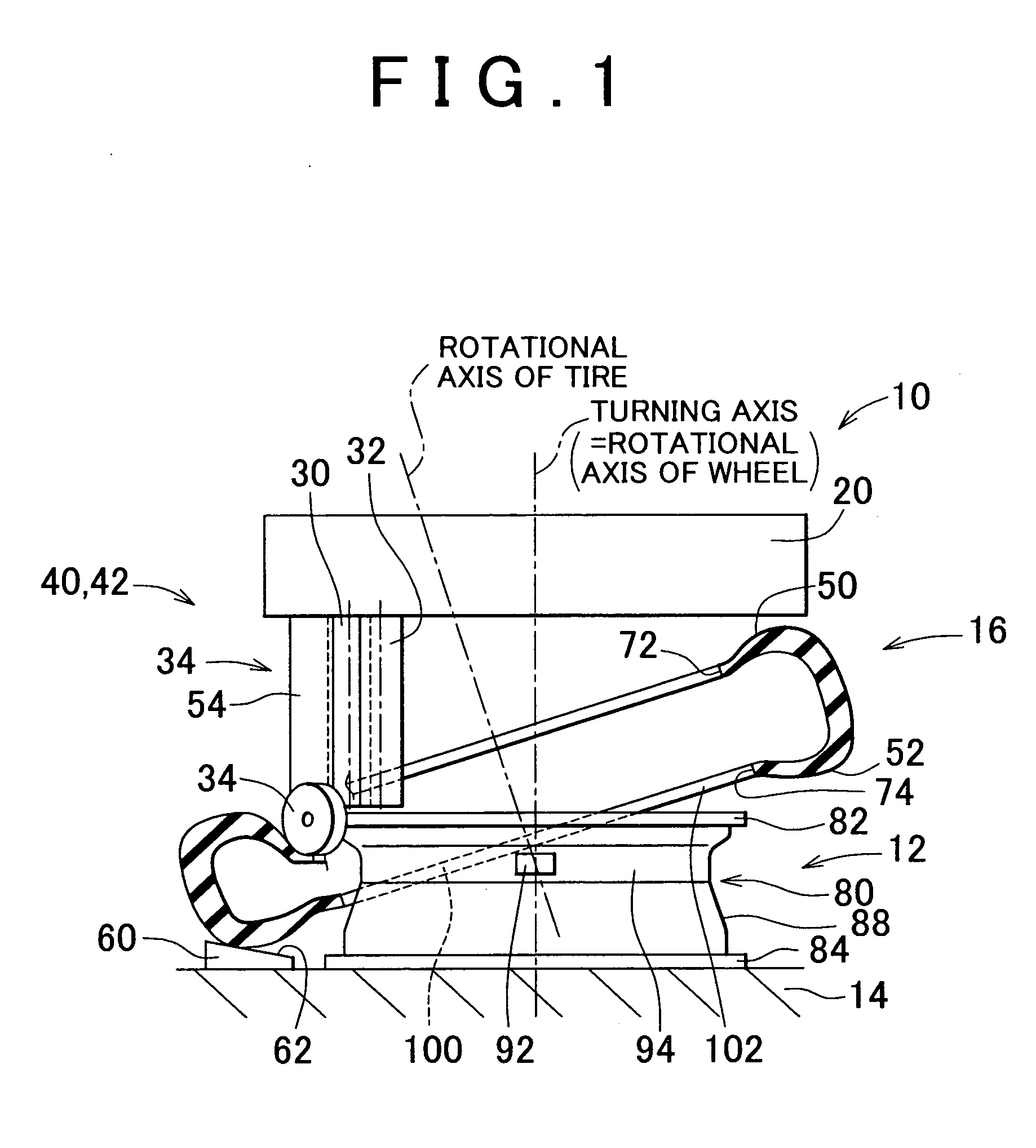
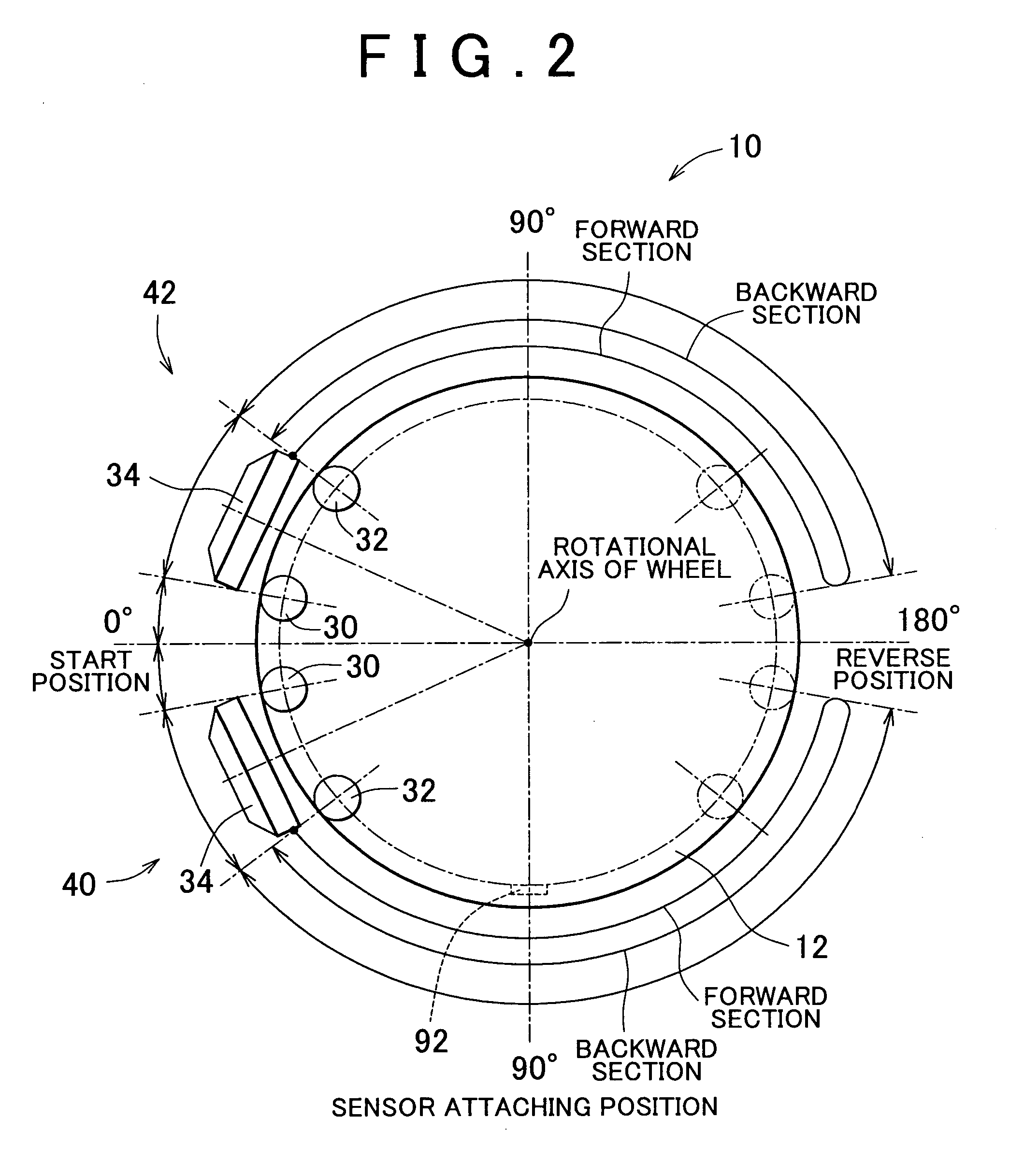
[0062]FIG. 1 is a side view showing a tire mounter 10 suitable for realizing a tire fitting method or device according to an embodiment of the invention. FIG. 2 is a plan view showing a main portion of the tire mounter 10.

[0063] As shown in FIG. 1, the tire mounter 10 includes a wheel fixture 14 on which a wheel 12 is centered, positioned and fixed while being placed horizontally. The tire mounter 10 further includes a head 20 which is operated to fit a tire 16 to the wheel 12 positioned by the wheel fixture 14.

[0064] The head 20 is designed so as to be movable up and down with respect to the wheel fixture 14 by a lifting / lowering device (not shown). The head 20 is moved to an operation position shown in FIG. 2, or a retraction position (not shown) located above the operation position. As shown in FIG. 2, the head 20 includes two roller sets 40 and 42 each of which...


PUM


Abstract

A wheel is positioned at an initial position by partially fitting a tire, from above, to the wheel in a slanting direction. From state where the wheel is positioned at the initial position, an expander, which expand paired bead portions of the tire in a radial direction of the wheel, is turned around the rotational axis of the wheel. In the initial position, the tire is positioned with respect to the wheel while an accessory does not overlap a lower portion of a lower bead portion that is provided at a lower position from among the paired bead portions in the initial position, the lower portion being provided below an upper rim flange portion that is provided at an upper position from among the paired rim flange portions, and the lower portion already being fitted to the wheel.

Description

INCORPORATION BY REFERENCE [0001] The disclosure of Japanese Patent Application No. 2003-334525 filed on Sep. 26, 2003, including the specification, drawings and abstract thereof, is incorporated herein by reference in its entirety. BACKGROUND OF THE INVENTION [0002] 1. Field of the Invention [0003] The invention relates to a method and a device for fitting a tire to a rim periphery of a wheel, to which an accessory is attached in advance. More particularly, the invention relates to a technology for preventing damage to the accessory caused by the tire fitting. [0004] 2. Description of the Related Art [0005] Various methods for fitting a tire to a wheel are known. An example of such methods is disclosed in Japanese Patent Laid-Open Publication No. 01-153311. According to such a method, generally, a tire is partially fitted, from above, to a horizontally placed wheel in a slanting direction. Then, an expander for expanding the tire in a radial direction is turned around the axis of t...

Claims


Application Information

Patent Timeline
IPC IPC(8): B60C23/04B60C25/12B60C19/00B60C25/138
CPCB60C23/0408B60C25/138B60C23/0494
Inventor KUSUNOKI, HIDEKI
Owner TOYOTA JIDOSHA KK
Why Eureka
Try Eureka