
Hydrogen sensor

a technology of hydrogen sensor and sensor, applied in the field of hydrogen sensor, can solve the problem that the sensor cannot detect a hydrogen concentration in a gas, and achieve the effect of preventing thermal interference between adjacent detection elements and being easy to d

Inactive Publication Date: 2005-03-31
HONDA MOTOR CO LTD
View PDF6 Cites 14 Cited by
  • Summary
  • Abstract
  • Description
  • Claims
  • Application Information

AI Technical Summary

Benefits of technology

[0011] Furthermore, since the hydrogen-absorbing alloy forming the detection element has fairly high selectivity for hydrogen, accuracy in concentration detection is increased.
[0013] By virtue of the above configuration, thermal interference between adjacent detection elements can be prevented.
[0015] The above configuration enables easy detection of changes in the property upon absorbing of hydrogen by the hydrogen-absorbing alloy forming the detection element.
[0017] According to the invention set forth in the second aspect, thermal interference between adjacent detection elements can be prevented. Accordingly, even when the hydrogen-absorbing alloy of either one of the detection elements produces heat upon absorbing of hydrogen, the adjacent detection element can be protected from thermally influence. That is, temperature control of the adjacent detection element can be protected from adverse effects.
[0018] According to the invention set forth in the third aspect, changes in the property upon absorbing of hydrogen by the hydrogen-absorbing alloy forming the detection element can be easily detected.

Problems solved by technology

The hydrogen sensor as disclosed in JP-A-10-73530 is suitable for detecting an amount of hydrogen, for instance, in such a way of being incorporated in equipment utilizing a hydrogen-absorbing alloy (e.g., hydrogen-absorbing alloy tank); however, the sensor is incapable of detecting a hydrogen concentration in a gas.

Method used


Image

  • Hydrogen sensor
  • Hydrogen sensor
  • Hydrogen sensor

Examples


Embodiment Construction

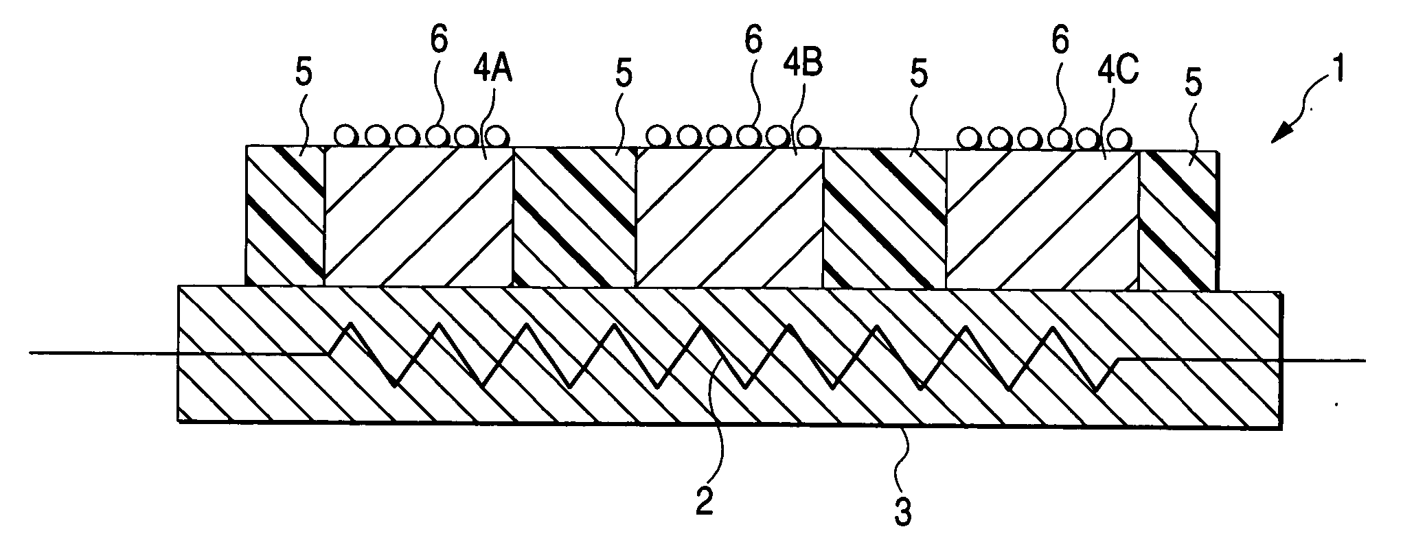
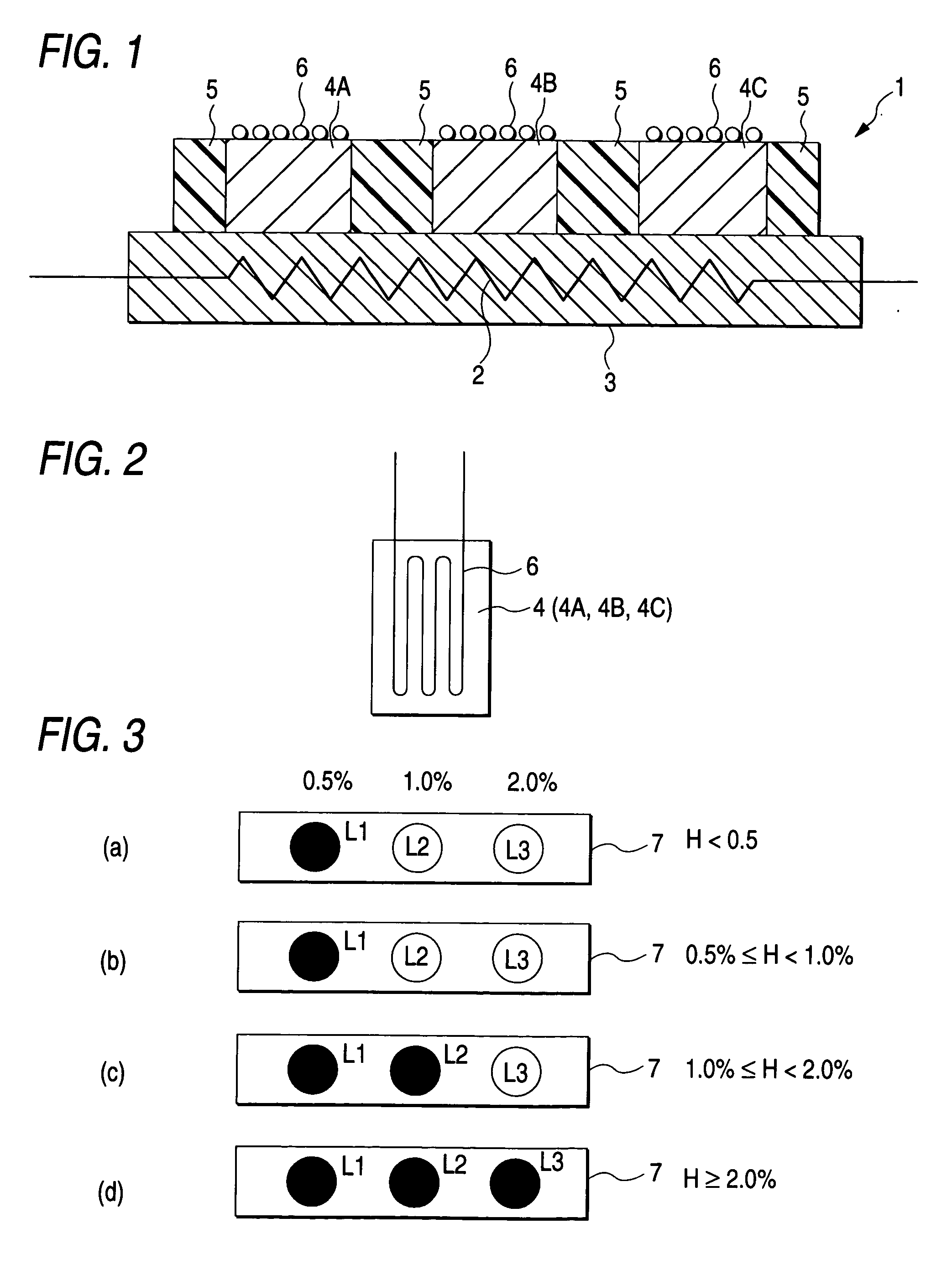
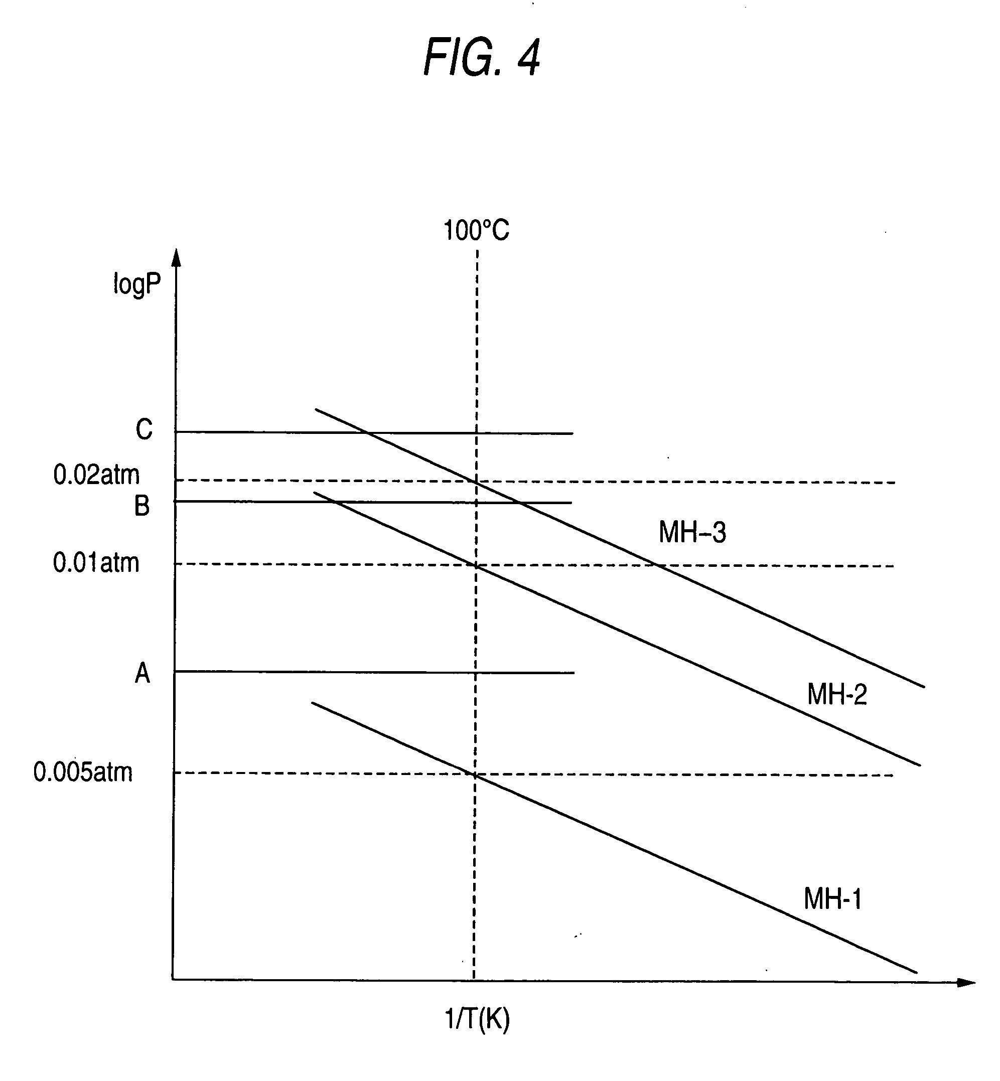
[0023] Embodiments of a hydrogen sensor according to the invention will be described with reference to FIGS. 1 to 4.

[0024] As shown in FIG. 1, the hydrogen sensor 1 comprises a substrate 3 in which a micro-heater is buried; a plurality of (in the embodiment, three) detection elements 4A, 4B, 4C (denoted as “detection elements 4” when particular identification thereof is not required) disposed on the upper surface of the substrate 3; heat insulation layers 5 (thermal insulating means) which are disposed around the respective detection elements so as to separate the adjacent detection elements 4, 4; and a strain gauge (detection means) 6 attached on the upper surface of each of the detection elements 4.

[0025] The substrate 3 serves as a support for integrally supporting the three detection elements 4A, 4B, 4C, and also serves as a temperature-maintaining device for holding the temperatures of the detection elements 4A, 4B, 4C at approximate equal values. A micro-heater 2 of the dete...


PUM


Abstract

A hydrogen sensor 1 includes detection elements 4A, 4B, 4C formed from hydrogen-absorbing alloys which exhibit different hydrogen-absorbing pressures at a given temperature; a strain gauge 6 which detects changes in volume upon absorbing of hydrogen by the detection elements 4A, 4B, 4C; a micro-heater 2 which controls the temperatures of all the detection elements 4A, 4B, 4C to approximate equal values; and a substrate 3.

Description

[0001] This application claims foreign priority based on Japanese Patent application No. 2003-340169, filed Sep. 30, 2003, the contents of which is incorporated herein by reference in its entirety. BACKGROUND OF THE INVENTION [0002] 1. Field of the Invention [0003] The present invention relates to a hydrogen sensor for detecting hydrogen concentration in a gas. [0004] 2. Description of the Related Art [0005] As a related art, a hydrogen sensor utilizing a hydrogen-absorbing alloy is disclosed in JP-A-10-73530. The hydrogen sensor has a hydrogen-absorbing alloy bonded on one surface of its substrate and has a strain gauge attached on the other surface thereof. In this arrangement, the distortion is produced in the substrate under a circumstance of volume expansion caused in the course of absorbing hydrogen by the hydrogen alloy. The hydrogen sensor detects the amount of said absorbed hydrogen by the strain gauge on the basis of a magnitude of distortion of a substrate. The hydrogen s...

Claims


Application Information

Patent Timeline
IPC IPC(8): G01N27/12G01N19/00G01N27/04G01N27/26G01N33/00
CPCG01N33/005
Inventor SHIMADA, TOSHIAKINUIYA, YOSHIO
Owner HONDA MOTOR CO LTD
Learn More