Method and apparatus for determining plasma impedance

a plasma and impedance technology, applied in the field of plasma processing, can solve the problems of inability to precisely install a voltage-current (“vi), inability to directly measure the rf impedance in the chamber, and inherently difficult to handle plasma, etc., and achieve the effect of accurate measurement of the rf impedan

Inactive Publication Date: 2005-03-31
TOKYO ELECTRON LTD
View PDF6 Cites 33 Cited by
  • Summary
  • Abstract
  • Description
  • Claims
  • Application Information

AI Technical Summary

Benefits of technology

The technical effect of this patent is that it provides a way to accurately measure how well a radio frequency (RF) signal passes through a layer of liquid called plasma when there are no electrical currents flowing through it. This can be useful for determining things like the thickness or composition of the plasma layer.

Problems solved by technology

This patent discusses the technical problem of measuring important parameters like plasma state and chamber conditions non-intrusively during plasma processing. Direct installation of voltage and current probes at the plasma-insulator interface or other locations along the RF drive transmission line faces practical difficulties due to limited space availability and requirements for vacuum tightness. Additionally, existing methods for evaluating chamber condition involve disassembling and cleaning chambers unnecessarily. There is also a concern about ensuring consistency in RF characteristic among various chambers after they undergo maintenance.

Method used


Image

  • Method and apparatus for determining plasma impedance
  • Method and apparatus for determining plasma impedance
  • Method and apparatus for determining plasma impedance

Examples


Embodiment Construction

[0021] Referring now to the drawings, where like reference numeral designations identify the same or corresponding parts throughout the several views, several embodiments of the present invention are next described.

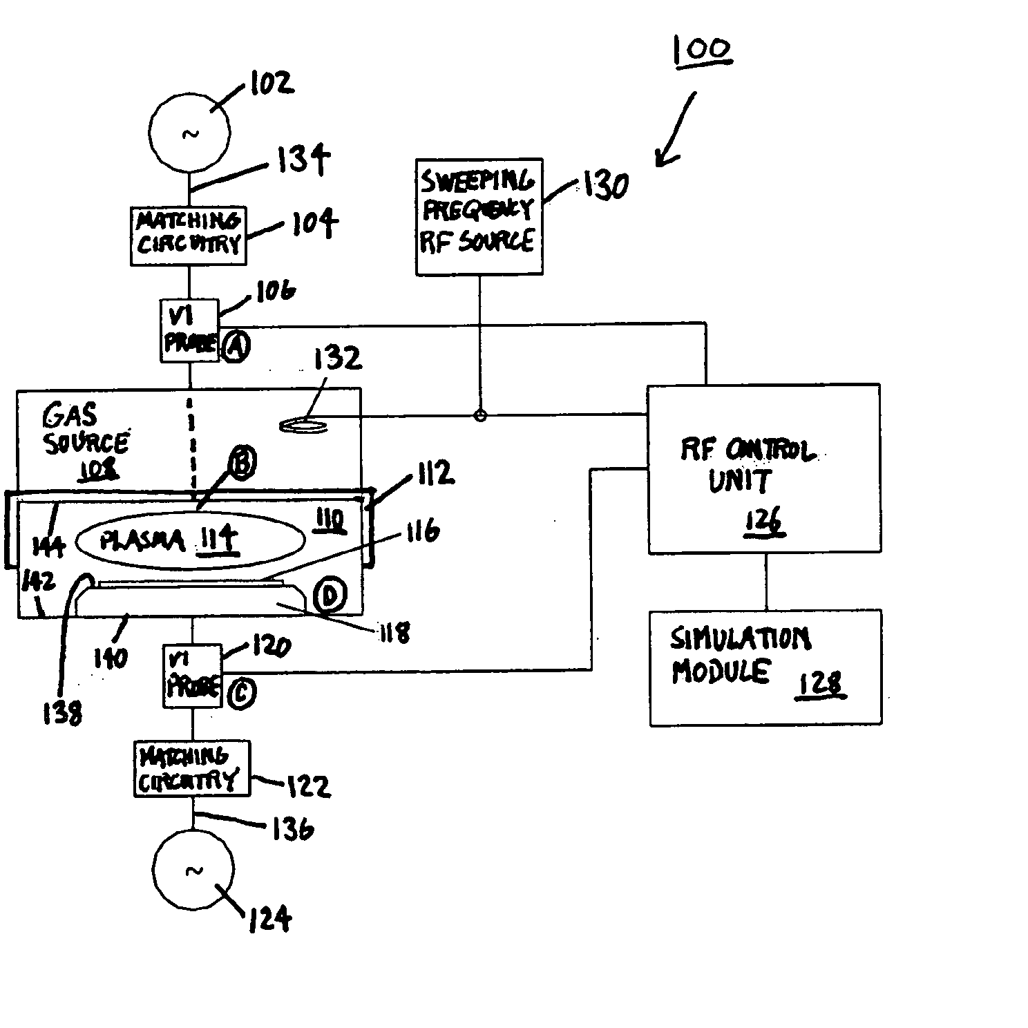
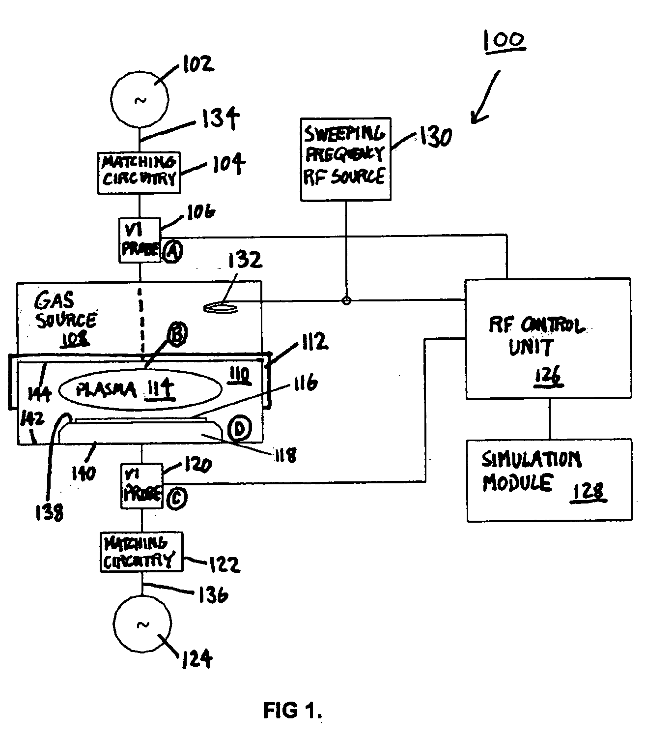
[0022]FIG. 1 illustrates a plasma processing system 100, which can be configured as an inductively coupled plasma (ICP) system, a capacitively coupled plasma (CCP) system, or a magnetically enhanced reactive ion etching (MERIE) system, for example. System 100 is primarily used to provide etching of a wafer 116 within chamber 110, where wafer 116 is supported by a support surface 138 of chuck 118. A bottom surface 140 of chuck 118 contacts an interior surface 142 of chamber 110. The etching, deposition, or other plasma processing of wafer 116 is performed using a plasma 114 created from gas provided by gas source 108.

[0023] Plasma 114 is driven by a main RF power source 102, which transmits RF power via an RF matching circuitry 104 to an excitation element 112. Excitatio...


PUM

PropertyMeasurementUnit
Electric potential / voltageaaaaaaaaaa
Frequencyaaaaaaaaaa
Plasma poweraaaaaaaaaa

Abstract

A plasma processing system, method, and computer readable medium for measuring plasma impedance. The system includes a chamber configured to contain a plasma and including a chuck within an interior area of the chamber, the chuck including a support surface and a bottom surface, and a first voltage-current probe positioned at a first position located exterior to the chamber and on a radio-frequency transmission line between the chamber and a power source. The system also includes a simulation module connected to the first voltage-current probe and arranged to solve, based on measurements transmitted from the first voltage-current probe, a radio-frequency model of the radio-frequency transmission line between the first position and a second position located within the chamber.

Description


Claims


Application Information

Patent Timeline
Owner TOKYO ELECTRON LTD
Why Eureka
Try Eureka