

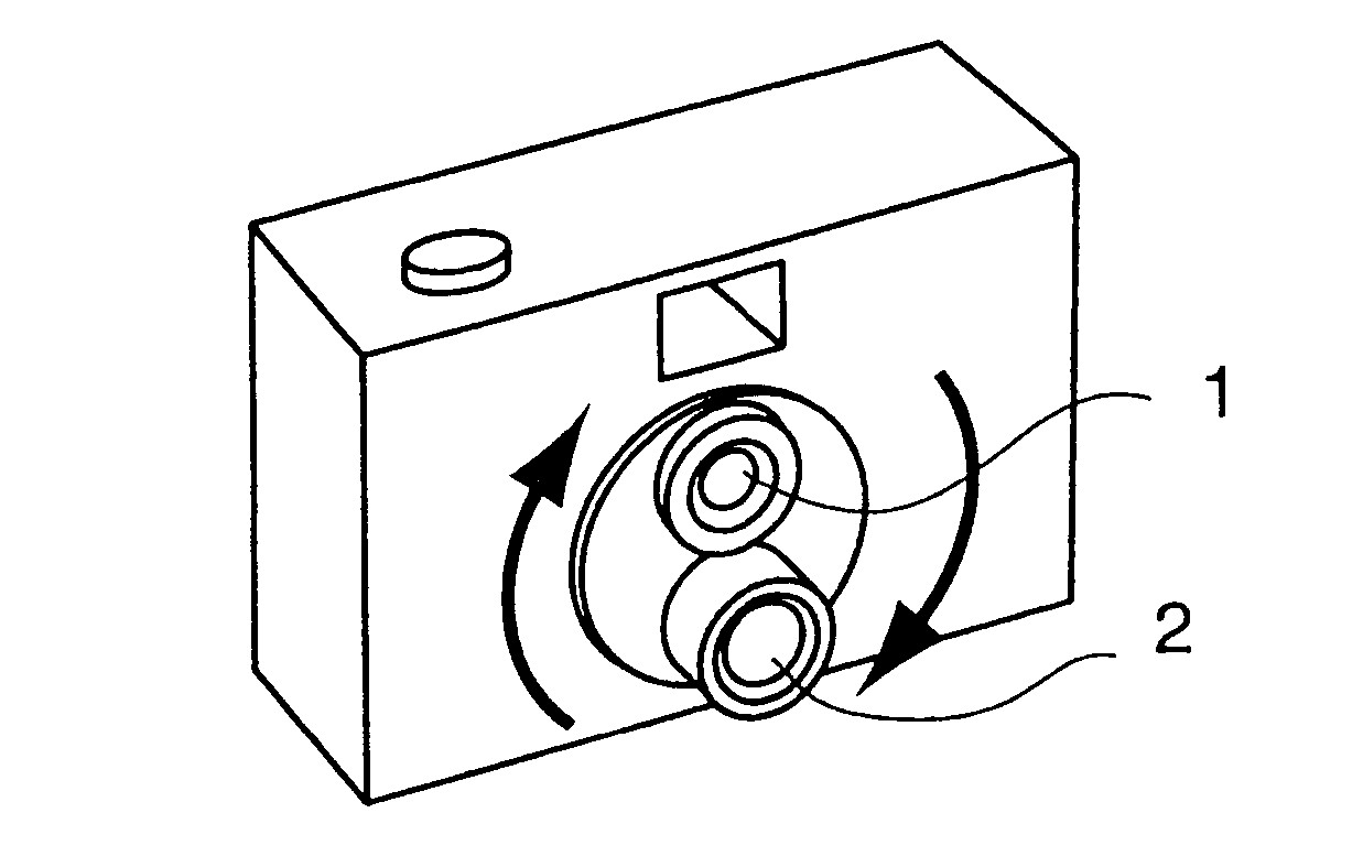
Lens turret with back focal length adjustment
a technology of lens turret and back focal length, which is applied in the field of optical equipment, can solve the problems of shortening the distance between lenses, difficult to compact the total size of the lens turret, and requiring the size of the lens modules to be extremely small
- Summary
- Abstract
- Description
- Claims
- Application Information
AI Technical Summary
Benefits of technology
Problems solved by technology
Method used
Image

Examples
Embodiment Construction
[0019] As described hereinbefore, the back focal length can be extended by inserting an additional element which is made of a glass, plastic or the like that has a higher refractive index than that of air. And the extension can be calculated using formulas as follows. [0020] Thickness of the additional element=T [0021] Refractive index of the additional element=RI [0022] Original Back focal length=BFL1 [0023] Extended distance=ED [0024] Extended back focal length=BFL2
T−T / RI=ED
and
BFL+ED=BFL2
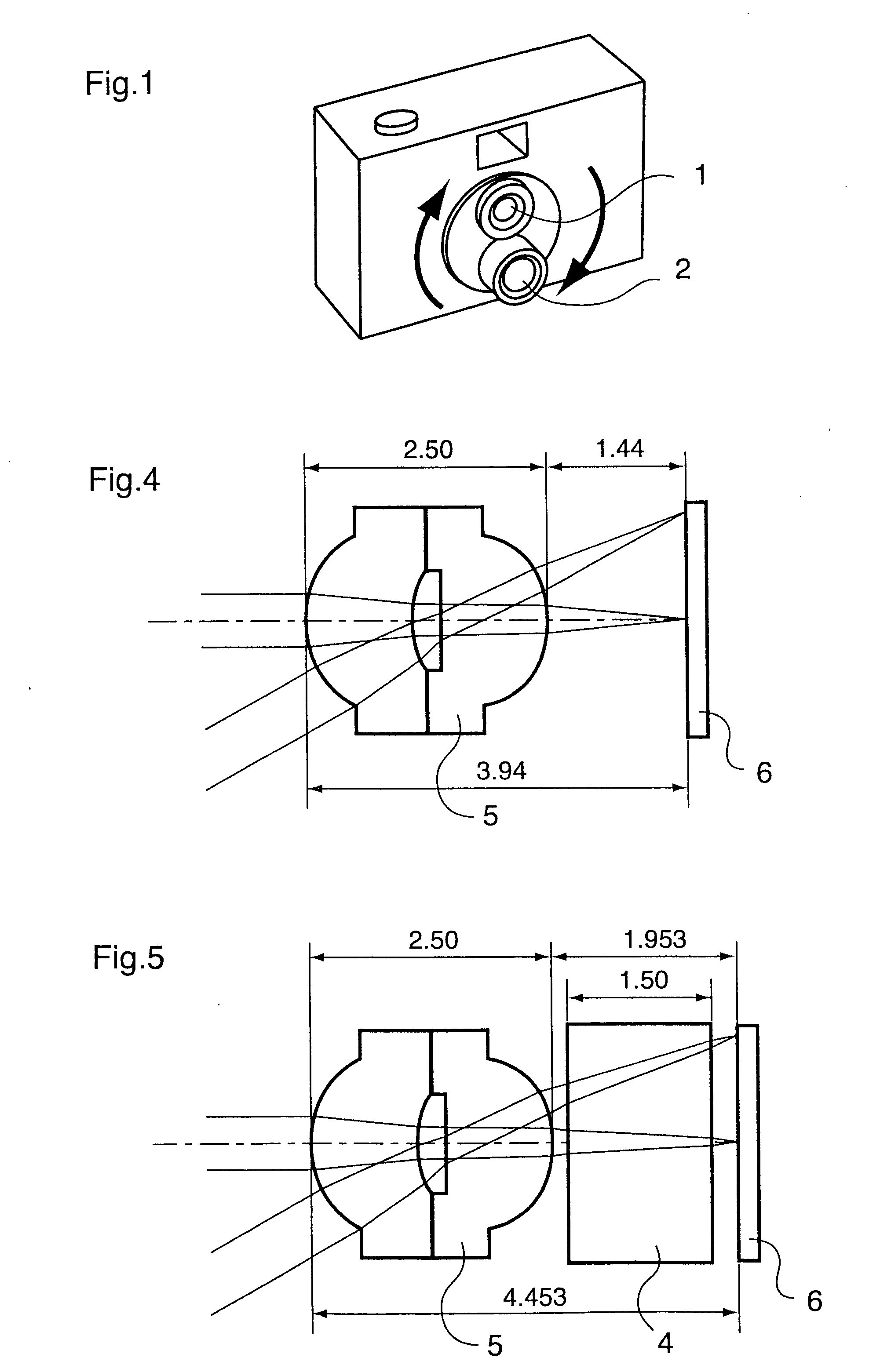
[0025] Using a sample design of a wide-angle lens as shown in FIG. 4, of which specifications are as follows, and an additional element of 1.5 mm thick made of optical glass with a refractive index of 1.52, if the back focal length adjustment is calculated, the result of calculation is as follows.
[0026] Lens specifications:
[0027] Fno=4.06 [0028] Focal length=2.15 mm [0029] Back focal length=1.44 mm [0030] Element=2 plastic aspherical elements
ED=1.5−1.5 / 1.52=0.513
and
BFL2=1.44(BFL1)+0.513=1...
PUM
 Abstract
Description
Claims
Application Information