Fuel pump

Inactive Publication Date: 2005-03-31
AISAN IND CO LTD +1
View PDF11 Cites 22 Cited by
  • Summary
  • Abstract
  • Description
  • Claims
  • Application Information

AI Technical Summary

Benefits of technology

[0009] The smaller the clearance between the rotor 121 and the magnets 105, the greater the magnetic flux passing through the rotor 121, and the higher the motor torque that can be obtained. Further, t

Problems solved by technology

A sufficiently high motor torque cannot be obtained.
Further, errors in the shape of each of the magnets 105 make it difficult to form a compl

Method used


Image

  • Fuel pump
  • Fuel pump
  • Fuel pump

Examples


Example

[0047] (First Embodiment)

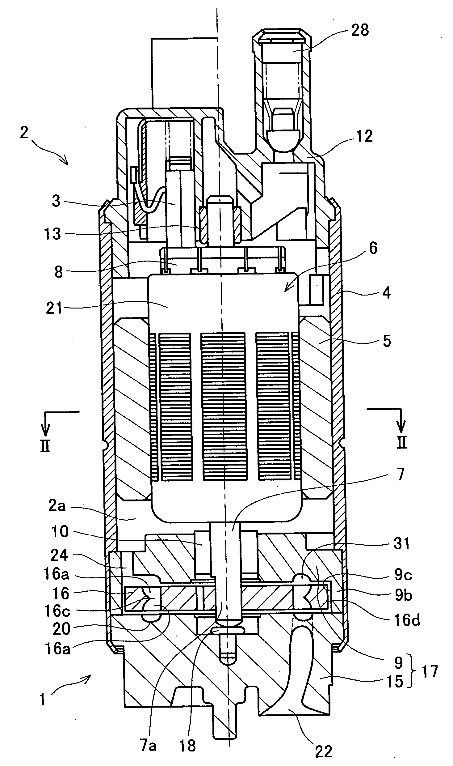
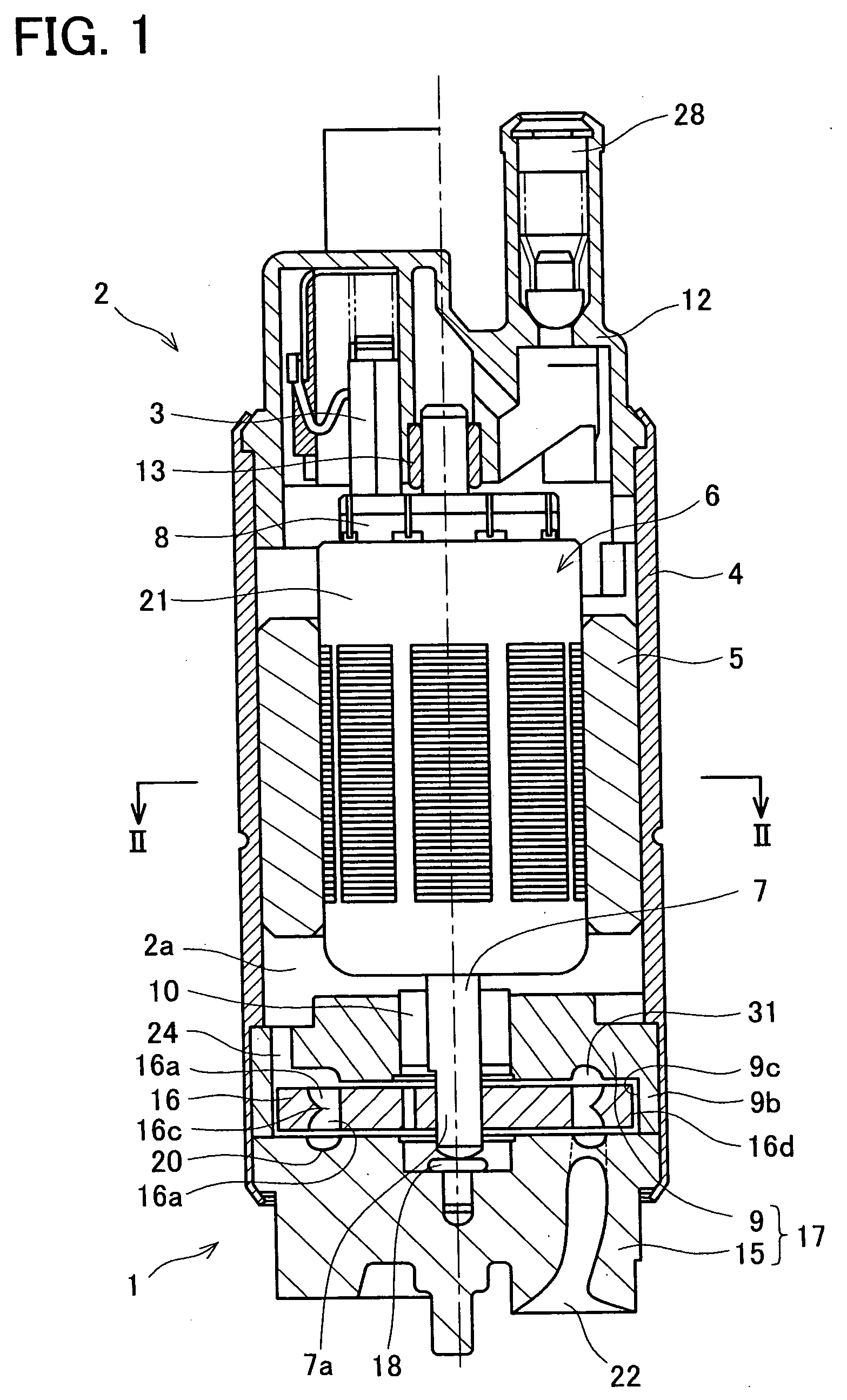
[0048] A first embodiment practicing the present invention is described referring to FIGS. 1 to 3.

[0049] A fuel pump of the present embodiment is a fuel pump used in a motor vehicle. The fuel pump is utilized within a fuel tank and is utilized for supplying fuel to an engine of the motor vehicle. As shown in FIG. 1, the fuel pump is composed of a pump section 1 and a motor section 2 for driving the pump section 1.

[0050] The pump section 1 is composed of a pump cover 9, a pump body 15, an impeller 16, etc. The pump cover 9 and the pump body 15 are formed by, for example, die casting aluminum, and the two are fitted together to form a casing 17 wherein the impeller 16 is housed.

[0051] The impeller 16 is formed in substantially a disc shape by means of resin molding. Recesses 16a are formed therein in an area extending. inwards for a determined distance from an outer circumference face 16d of the impeller 16. The recesses 16a that are repeated in the circum...

Example

[0070] (Second Embodiment)

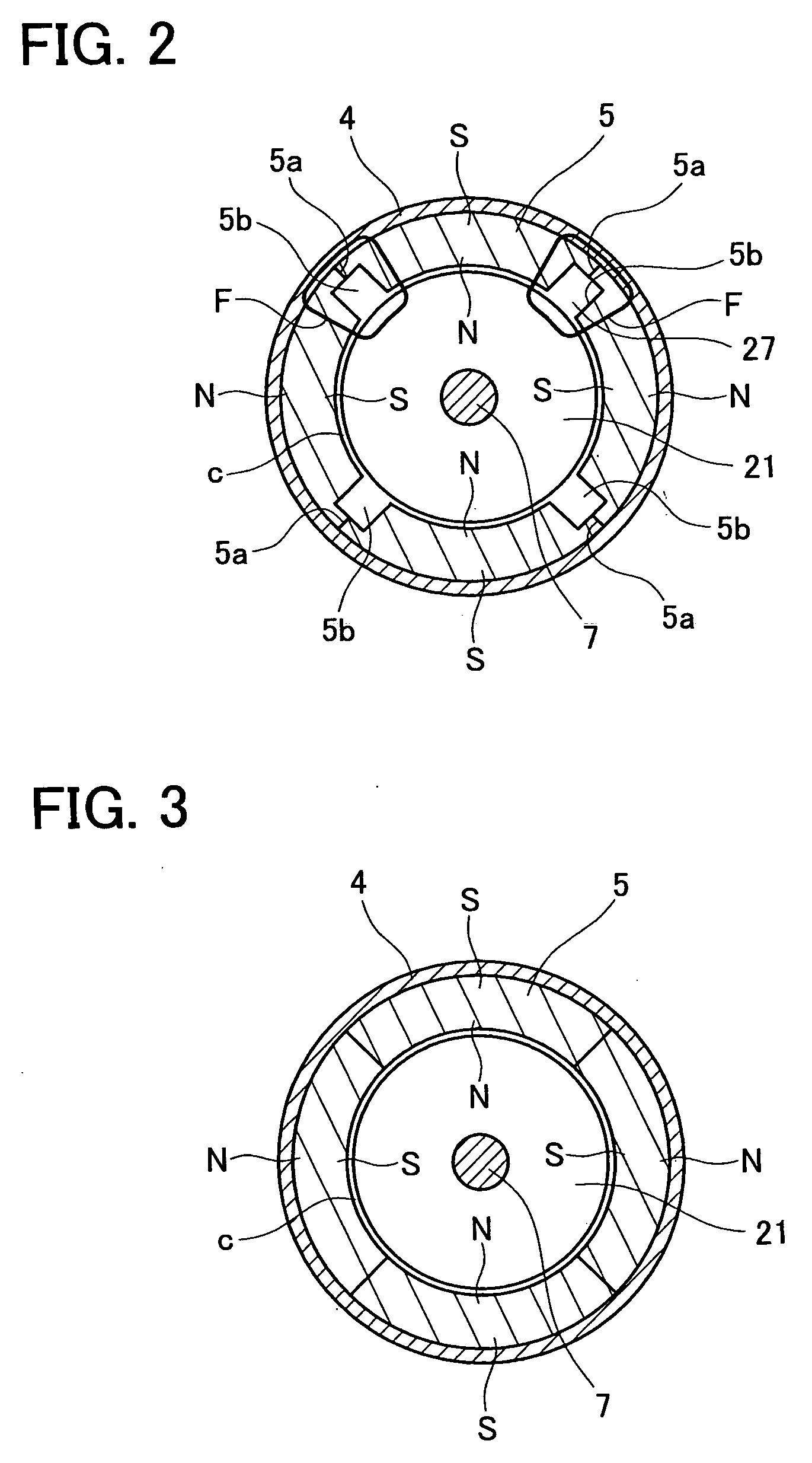
[0071] A second embodiment for practicing the present invention will be described. The present embodiment has approximately the same configuration as that of the first embodiment, and differs therefrom only in the shape of the magnet of the motor section. Consequently, only the portion differing from the first embodiment will be described here using FIG. 4, which corresponds to the cross-sectional view along the line II-II of FIG. 1. Components identical with those of the first embodiment have the same reference numbers assigned thereto.

[0072] As shown in FIG. 4, grooves 35b that extend in the axial direction are formed at locations where boundary lines 35a between poles of a magnet 35 are exposed at the outer circumference face. Spaces formed by the grooves 35b and the inner circumference face of the housing 4 are utilized as fuel passages 37. When the highly pressurized fuel delivered from the pump section 1 to the inner space 2a of the motor section 2 ...

Example

[0075] (Third Embodiment)

[0076] A third embodiment for practicing the present invention will be described. The present embodiment has approximately the same configuration as that of the first embodiment and the second embodiment, and differs therefrom only in the shape of the magnet of the motor section. Consequently, only the portion differing from the first embodiment will be described here using FIG. 5, which corresponds to the cross-sectional view along the line II-II of FIG. 1. Components identical with those of the first embodiment have the same reference numbers assigned thereto.

[0077] As shown in FIG. 5, holes 45b that extend in the axial direction are formed within the interior of a magnet 45 at locations where boundary lines 45a between poles of the magnet 45 are located. The holes 45b are utilized as fuel passages 47. When the highly pressurized fuel delivered from the pump section 1 to the inner space 2a of the motor section 2 is delivered towards the discharge port 28...


PUM


Abstract

A fuel pump with improved pumping performance having a high motor torque and a sufficient cross sectional area of fuel passage is provided.
The motor section (2) of the fuel pump has a columnar rotor (21) having a shaft (7) for rotating the pump section (1), and a ring magnet (5, 35, 45, 55, 65, 75, 85) surrounding an outer circumference face of the rotor (21). There is provided a minute clearance between the rotor (21) and the magnet (5, 35, 45, 55, 65, 75, 85). The motor section (2) further has a cylindrical yoke (4, 34, 46, 56, 66) surrounding and contacting an outer circumference face of the magnet (5, 35, 45, 55, 65, 75, 85). A fuel passage (27, 37, 47, 57,67, 77, 87, 97, 127) having a sufficient cross sectional area is formed at a location removed from a magnetic path along which a substantial portion of magnetic flux (F) flows between the rotor (21), the magnet (5, 35, 45, 55, 65, 75, 85), and the yoke (4, 34, 46, 56, 66).

Description

CROSS REFERENCE TO RELATED APPLICATION [0001] This application claims priority under the Paris convention to Japanese Patent Application number 2003-338504, which was filed on Sep. 29, 2003, and entire content of which are hereby incorporated by reference. BACKGROUND OF THE INVENTION [0002] 1. Field of the Invention [0003] The present invention relates to a fuel pump for drawing in fuel such as gasoline etc., increasing the pressure thereof, and discharging the pressurized fuel. [0004] 2. Description of Related Art [0005] A fuel pump comprises a pump section and a motor section for rotating the pump section, these being provided within a housing. The motor section comprises an armature and a magnet. The armature has a shaft supported in a manner allowing rotation, a rotor fixed to the shaft, and a commutator. The rotor comprises a core having laminated iron plates, and coils wound around the core. Ends of each coil are connected with the commutator. An end of the shaft fits with the...

Claims


Application Information

Patent Timeline
IPC IPC(8): F02M37/08F04D5/00F04D7/02F04D29/44H02K1/12H02K1/17H02K1/32H02K5/12
CPCH02K1/12H02K5/12H02K1/32H02K1/17
Inventor IKEYA, MASAKIHASHIMOTO, YOJI
Owner AISAN IND CO LTD
Why Eureka
Try Eureka