Signal transmission apparatus and signal transmission method

a signal transmission apparatus and signal transmission technology, applied in multiplex communication, power management, high-level techniques, etc., can solve the problems of occupying a lot of space for power amplifiers capable of outputting high-power signals, affecting the efficiency of signal transmission, and reducing the size of signal transmission apparatuses, so as to achieve the effect of reducing the power of transmission

Inactive Publication Date: 2005-03-31
NTT DOCOMO INC
View PDF9 Cites 43 Cited by
  • Summary
  • Abstract
  • Description
  • Claims
  • Application Information

AI Technical Summary

Benefits of technology

The present invention is conceived to overcome the above-described problems, and it is an object of the present invention to provide a signal transmission apparatus and a signal transmission method that can control the transmit power when transmitting a common channel by omnidirectional sector transmission to a mobile terminal located in the service area of a wireless base station.
With this arrangement, a first signal, such as a common channel, dose not have to be transmitted to the entire area of the geographical area all the time, because it can be transmitted using a prescribed beam pattern directed in a specific direction. Consequently, transmit power can be reduced.

Problems solved by technology

However, such a power amplifier capable of outputting a high power signal occupies a lot of space, which goes against the demand for reducing the size of the signal transmission apparatus.
This is also against the demand for miniaturization.
This drawback becomes conspicuous as the power required to transmit the common channel (that is, the portion of the entire transmit power) increases.
This limits the sector capacity.

Method used


Image

  • Signal transmission apparatus and signal transmission method
  • Signal transmission apparatus and signal transmission method
  • Signal transmission apparatus and signal transmission method

Examples


Embodiment Construction

The present invention is described in detail below in conjunction with the attached drawings.

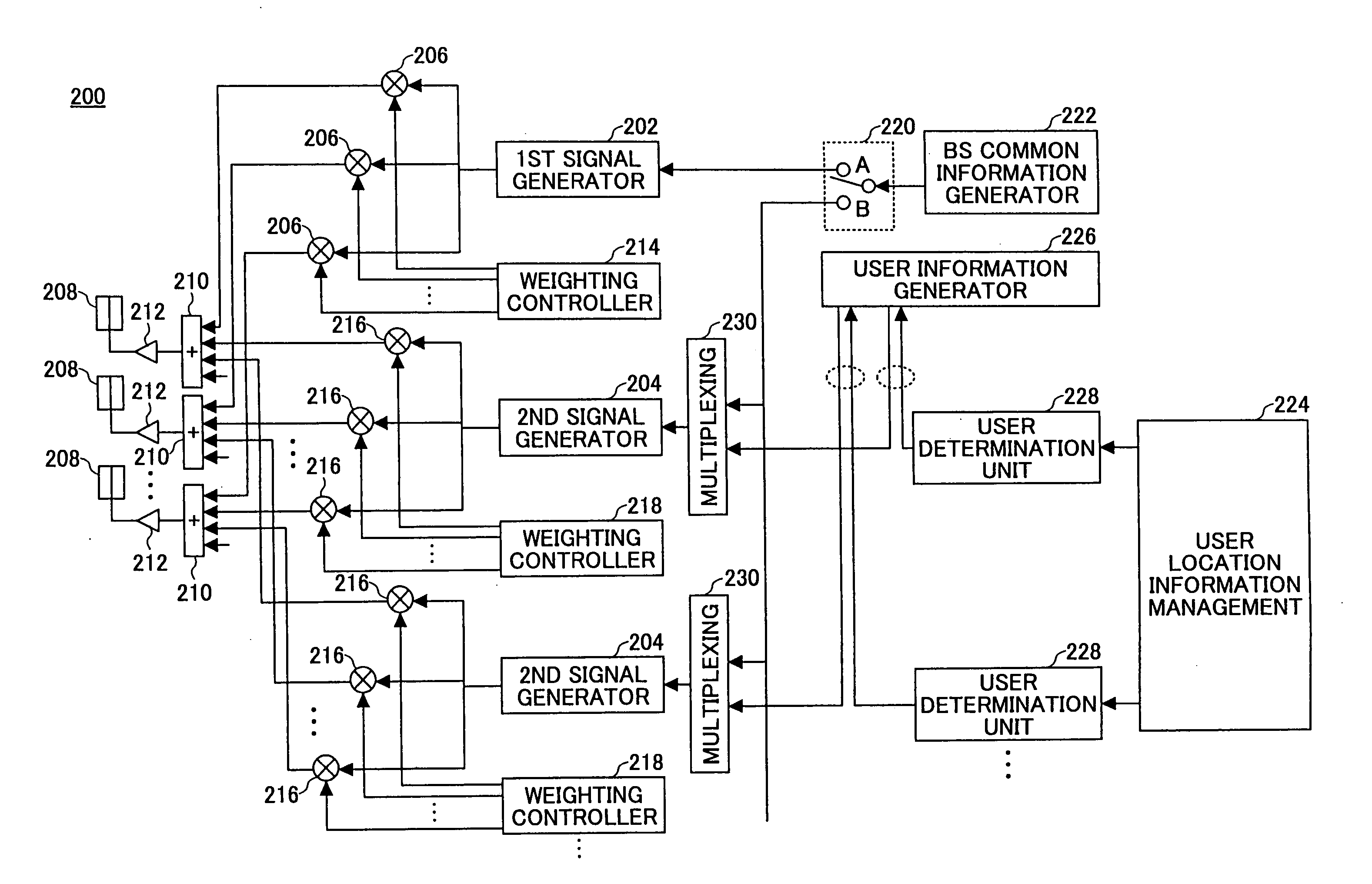
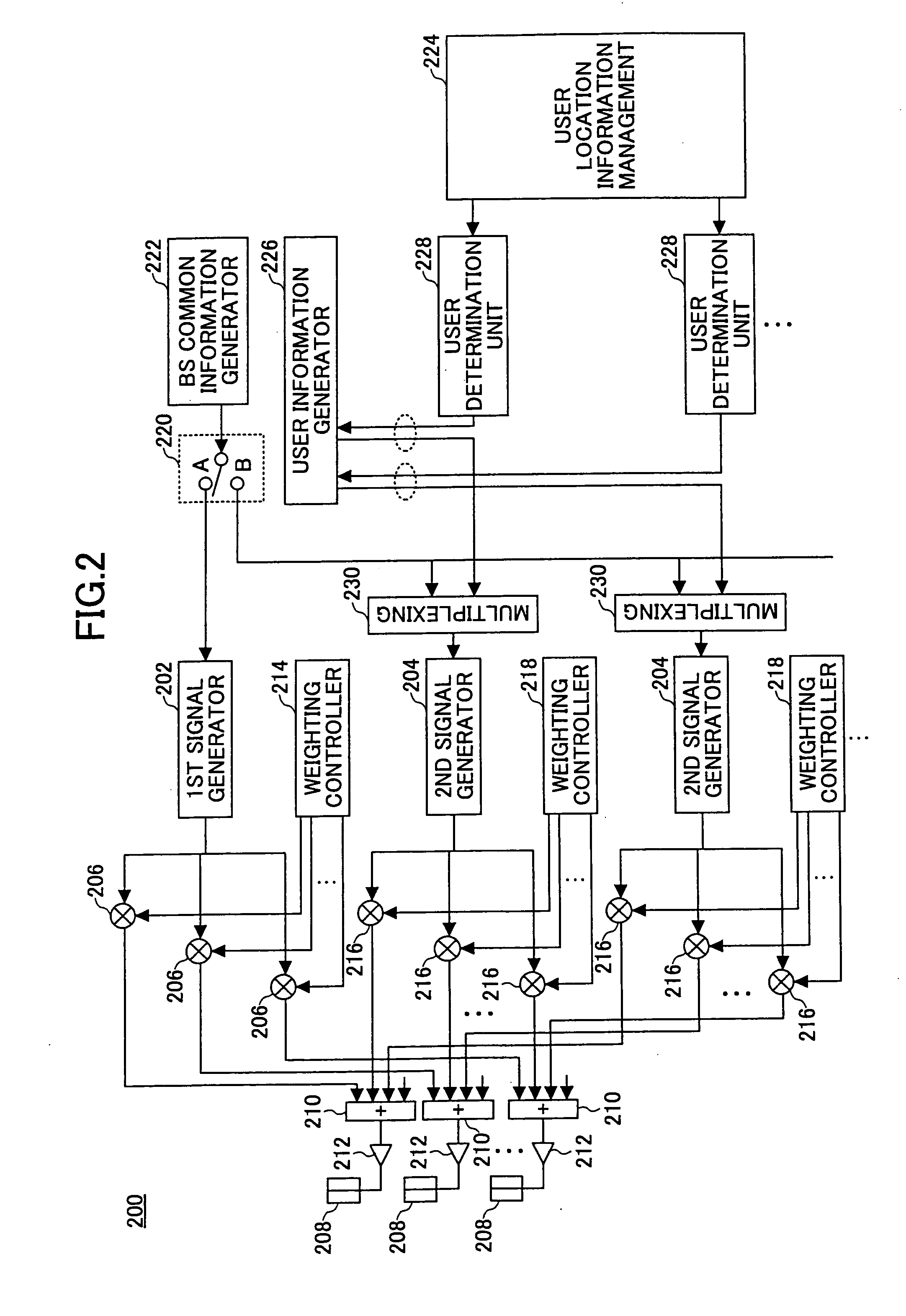
FIG. 2 is a functional block diagram of a signal transmission apparatus according to an embodiment of the invention. The signal transmission apparatus 200 includes a first transmission signal generator 202 and second transmission signal generators 204. The first and second transmission signal generators 202 and 204 generate transmission signals such that these signals can be distinguished from each other by adjusting frequencies, time slots, or spread codes, the details of which will be explained later. The outputs of the first transmission signal generator 202 are connected to the weighting adjustors 206 provided to the respective antenna elements 208. The output of each of the weighting adjustors 206 is supplied to a signal synthesizer 210 provided for each of the antenna elements 208. Between the antenna element 208 and the associated signal synthesizer 210 is provided a power amplifier...


PUM


Abstract

A signal transmission apparatus for transmitting a signal using multiple antenna elements comprises a transmission signal generator configured to convert at least one of a first signal addressed to an arbitrary mobile terminal belonging to a geographical area and a second signal addressed to a specific mobile terminal located in a part of the geographical area into one or more transmission signals to be transmitted using a prescribed beam pattern; a weighting adjustor configured to weight said one or more transmission signals for each of the antenna elements to define the prescribed beam pattern; and a signal synthesizer provided for each of the antenna elements and configured to synthesize the weighted transmission signals.

Description

BACKGROUND OF THE INVENTION The present invention generally relates to a wireless communication technique, and more particularly, to an apparatus and a method for transmitting signals to one or more users located in a prescribed geographical area. In the field of wireless communications, various studies are made of the next-generation communication schemes, and researches are also conducted on these communication schemes. In particular, the adaptive array antenna (AAA) technique is one of the technologies that is drawing attention because of its possibility of increasing the capacity for number of subscribers. An adaptive array antenna includes multiple antenna elements (such as dipole antennas) arranged in an array. By adaptively controlling the weight for each of the antenna elements, the antenna gain can be increased in a specific direction. For example, the antenna gain is increased in a direction to which a signal is forwarded to a counterpart communicating node, while the a...

Claims


Application Information

Patent Timeline
Patent Type & Authority Applications(United States)
IPC IPC(8): H01Q3/26H01Q3/30H01Q25/00H04B1/707H04B7/04H04B7/06H04B7/26H04J13/00H04W16/28H04W52/28H04W52/32
CPCH01Q3/26H01Q3/2605H01Q3/30H04B7/0617H04B7/0408H04B7/0452H04B7/0456H01Q25/00Y02D30/70
Inventor HIGUCHI, KENICHIIHARA, TAISUKESAWAHASHI, MAMORU
Owner NTT DOCOMO INC
Why Eureka
Try Eureka