Baffled attic vent including method of making and using same

a technology of attic vents and baffling, which is applied in ventilation systems, lighting and heating apparatus, heating types, etc., can solve the problems of poor air circulation, restricting air flow, and counter-productive restriction, and achieves the effect of greater air flow

Active Publication Date: 2005-04-07
CZAJKOWSKI LAURENCE P
View PDF30 Cites 31 Cited by
  • Summary
  • Abstract
  • Description
  • Claims
  • Application Information

AI Technical Summary

Benefits of technology

[0009] The present invention employs an integral baffle surface disposed on a roof facing side of the vent for directing the air flow of vented air. In an improved embodiment, the air flow is only slightly affected, creating a resulting air flow of approximately 95-125 CFM. When compared to baffled vent designs having supporting structures of the “egg shell” or longitudinal pyramid design (such as prior art competitor designs A, B and C of FIGS. 5-7), the air vent baffles of the present invention produce significantly greater air flow.

Problems solved by technology

Unfortunately, thicker attic insulation can lead to poor air circulation when the spaces between the roofjoists and the top wall plate of the building are closed or obstructed.
The features used to stiffen such vents, such as ribs and longitudinal stiffeners, unfortunately also restrict air flow.
In some cases, such a restriction is counter productive to the purpose of the vent, but is unknown to the homeowner.

Method used


Image

  • Baffled attic vent including method of making and using same
  • Baffled attic vent including method of making and using same
  • Baffled attic vent including method of making and using same

Examples


example i

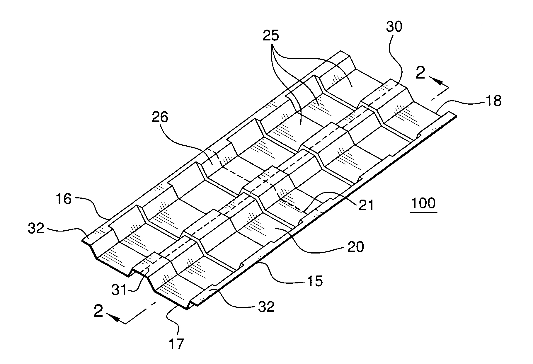
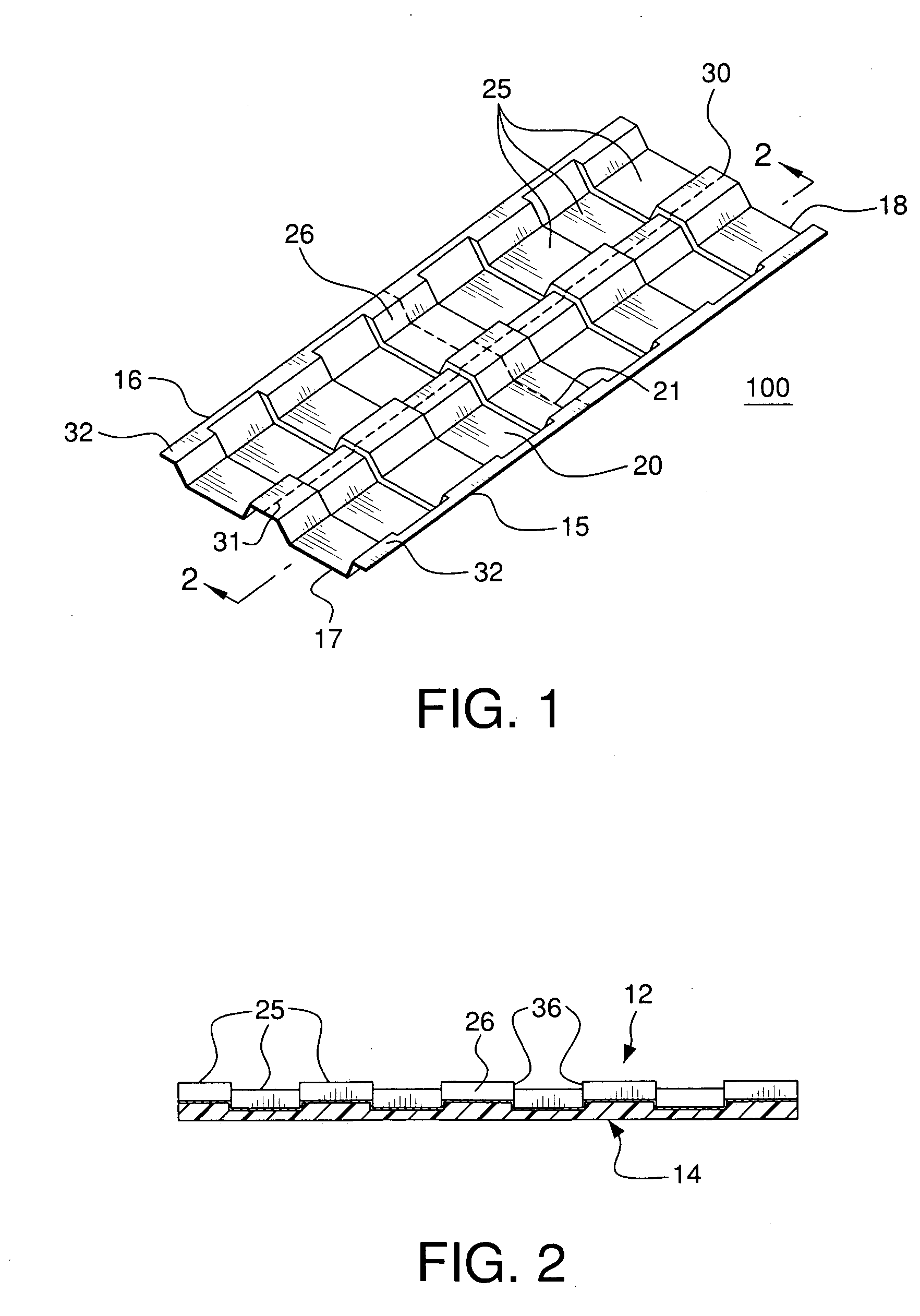
[0035] Computational fluid dynamic analyses were performed on the illustrative example of FIG. 1 and compared with prior art competitive designs A, B, and C of FIGS. 7, 5 and 6, respectively. The proposed attic air vent 100 of this invention has only a slight increase in air flow resistance with transverse stiffeners placed to cross the open channels. In the preferred embodiment, the present vent 100 does not use supports which extent substantially into the air path, as shown in competitive designs A and B, nor does it use longitudinal supports disposed substantially in the air path, like competitive design C. This results in improved natural convection air flow under a 5 Pa air pressure differential, as analyzed by the computational, computer analysis, as found in FIG. 8. The design of FIG. 1 showed improvement of about 31-147% in air flow over competitive designs, with an air-flow range of about 95-125 CFM preferred, and a target of about 118.6 CFM. This can be accomplished with s...


PUM


Abstract

Baffled attic vents and methods of their use and manufacture are provided. The baffled air vent of this invention includes an elongated member having a roof facing side and an attic space facing side, a pair of longitudinal side portions, first and second transverse ends, and at least one central panel portion. The vent defines at least one channel on the roof facing side thereof, for directing ventilated air. The channel includes a bottom portion having an integral baffled surface thereon. The vent further has an installed, convective air flow reading, under a 5 Pa air pressure differential, of at least about 95 CFM. Further embodiments contain separation means for permitting the attic vent to be separated by hand in a transverse or longitudinal direction.

Description

FIELD OF THE INVENTION [0001] This invention relates to baffled air vents located between adjacent roof rafters of a structure, and particularly to baffled air vents having improved, installed convective air flow readings. BACKGROUND OF THE INVENTION [0002] With an increasing emphasis on energy efficiency, attic insulation has often been supplemented by blown, loose-fill insulation, or by additional or thicker insulation bats to prevent heat loss in the winter and cool air loss in the summer. Unfortunately, thicker attic insulation can lead to poor air circulation when the spaces between the roofjoists and the top wall plate of the building are closed or obstructed. These spaces must be left open to provide air flow between the soffit area and the attic space, for reducing excess humidity and heat, which have been known to deteriorate roofing and structural components. In order to keep this area open, baffled attic vents have been used. [0003] The purpose of an attic vent is to prev...

Claims


Application Information

Patent Timeline
Patent Type & Authority Applications(United States)
IPC IPC(8): E04D13/17
CPCE04D13/17
Inventor DUNCAN, RICHARD S.CIEPLISKI, DUSTIN
Owner CZAJKOWSKI LAURENCE P
Why Eureka
Try Eureka