
Thin camera having sub-pixel resolution

a subpixel resolution and camera technology, applied in the field of thin cameras having subpixel resolution, can solve the problems of limited pixel size and insufficient power in such a scaled down system, and achieve the effect of low transmittance function and high resolution

Inactive Publication Date: 2005-04-07
NANCHANG O FILM OPTICAL ELECTRONICS TECH CO LTD
View PDF4 Cites 24 Cited by
  • Summary
  • Abstract
  • Description
  • Claims
  • Application Information

AI Technical Summary

Benefits of technology

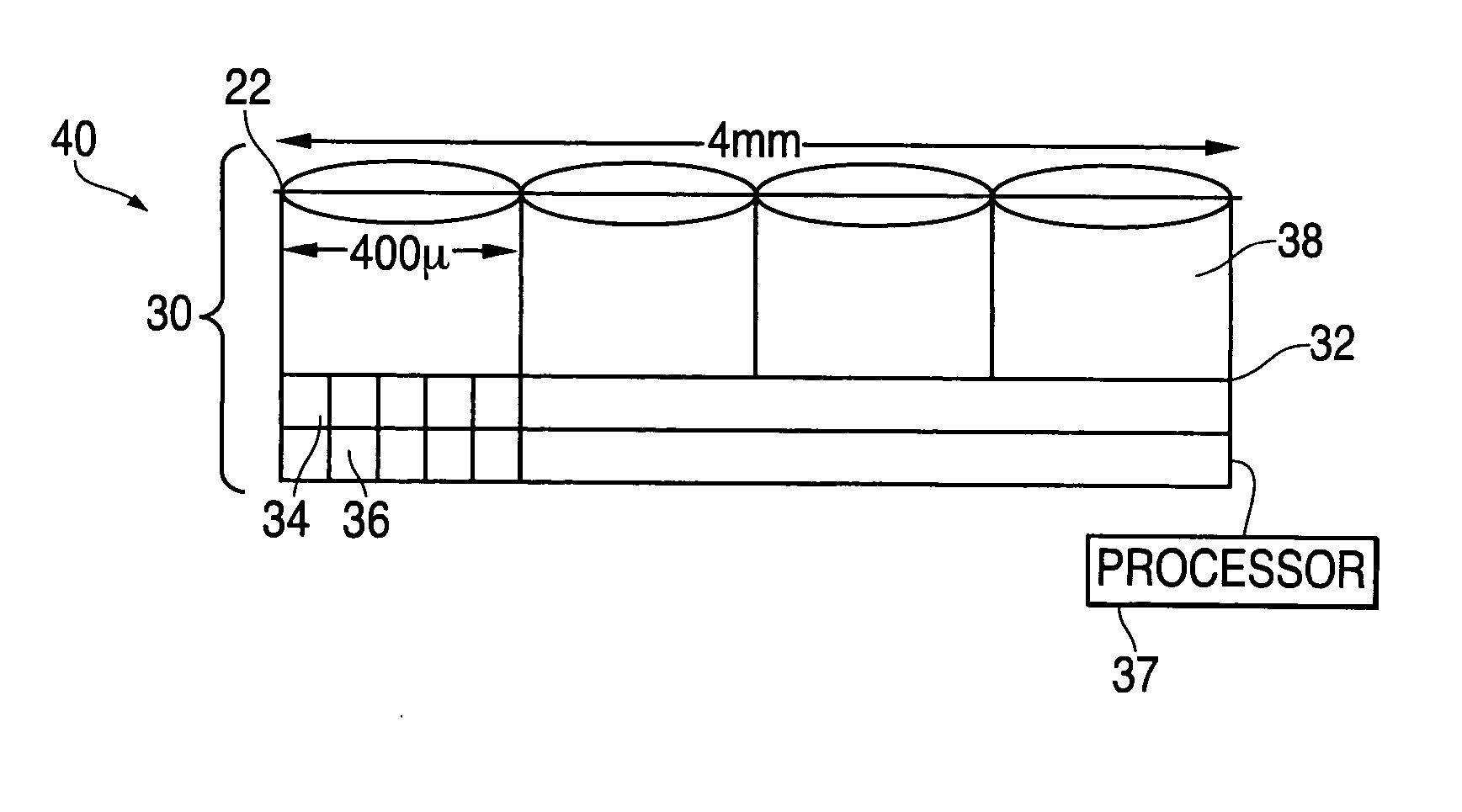
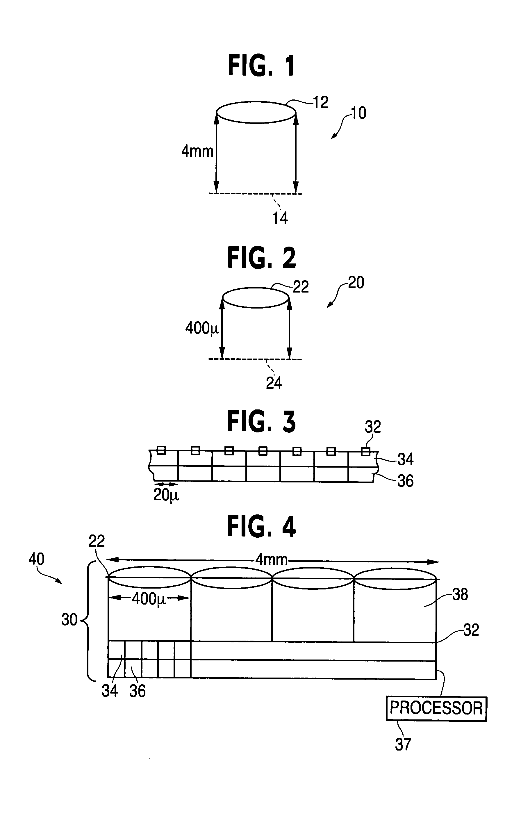
[0004] At least one of the above and other features of the present invention may be realized by providing an imaging system having an array of lenses, a plurality of sensors for each lens, and a plurality of macro-pixels of size dxdy. Each sensor has a single detection element of size pxpy, with the center-to-center spacing of the sensor elements being dx in the x-direction and dy in the y-direction. The plurality of sensors are adjacent to an image plane of a corresponding lens. Each macro-pix

Problems solved by technology

However, this scaled down pixel size may be limited by availability and / or price of current sensors.
Further, there is not enough power in such a scaled down system.

Method used


Image

  • Thin camera having sub-pixel resolution
  • Thin camera having sub-pixel resolution
  • Thin camera having sub-pixel resolution

Examples


Embodiment Construction

[0014] U.S. Provisional Application No. 60 / 507,579, filed on Oct. 1, 2003, and entitled: “THIN CAMERA” is incorporated herein by reference in its entirety.

[0015] The present invention will now be described more fully hereinafter with reference to the accompanying drawings, in which preferred embodiments of the invention are shown. The invention may, however, be embodied in different forms and should not be construed as limited to the embodiments set forth herein. Rather, these embodiments are provided so that this disclosure will be thorough and complete, and will fully convey the concept of the invention to those skilled in the art. In the drawings, the thickness of layers and regions are exaggerated for clarity. It will also be understood that when a layer is referred to as being “on” another layer or substrate, it may be directly on the other layer or substrate, or intervening layers may also be present. Further, it will be understood that when a layer is referred to as being “u...


PUM


Abstract

A thin camera having sub-pixel resolution includes an array of micro-cameras. Each micro-camera includes a lens, a plurality of sensors of size p, and a plurality of macro-pixels of size d having a feature of size q. The feature size q smaller than p and provides a resolution for the micro-camera greater than p. The smallest feature in the micro-cameras determines the resolution of the thin camera. Each macro-pixel may have any array of m features of size q, where q=d / m. Additional micro-cameras may be included to increase power.

Description

BACKGROUND [0001] There is a need for a thin camera or imaging system for many applications. An approach to realizing a thin camera with sufficient resolution involves scaling an imaging system of a conventional camera 10, shown in FIG. 1, down by some factor. In the following example, the conventional camera is an f / 1 camera having a lens 12 with a focal length f, here a 4 mm focal length, and a detector array 14, here having 200×200 pixels with 20 microns per pixel. The resolution of this camera is given by 1 / (20 microns) or 50 lines per mm. The desired scaling factor in this example is ten. The resulting scaled down thin camera 20, shown in FIG. 2, includes a micro-lens 22, here having a 400-micron focal length and a micro-detector array 24, here being a 200×200 array of 2 microns per pixel. Here the pixels are assumed to have the same dimension in both the x- and y-direction. [0002] More generally, assume the focal plane has nx pixels or sensors of a size px in the x-direction a...

Claims


Application Information

Patent Timeline
IPC IPC(8): H04N5/225H04N5/335H04N5/369
CPCH04N5/335H04N3/1593H04N25/41H04N25/00
Inventor FELDMAN, MICHAEL R.TE KOLSTE, ROBERT
Owner NANCHANG O FILM OPTICAL ELECTRONICS TECH CO LTD
Learn More