System and method for controlling a utility meter

Active Publication Date: 2008-04-10
CARINA TECH
View PDF98 Cites 69 Cited by
  • Summary
  • Abstract
  • Description
  • Claims
  • Application Information

AI Technical Summary

Benefits of technology

[0011] The information may be communicated wirelessly or through the power line carrier between the collar-based meter device and the internal customer display unit in a real time environment. This information includes real time kilowatt hours, voltage profile, total harmonics distortion and power factor. This information is measured over a 1 minute, 5 minute, 15 minute interval basis, or variable time basis. The voltage profile may be presented over the same time frames as well. Temperature inside the collar device is also available. The system of the present invention includes the ability to display energy consumption by appliance and provide the

Problems solved by technology

Obtaining meter readings can be a laborious and costly process for the utility, as historically meter reading required individuals going house to house and manually reading the meter and recording the results.
A disadvantage of the historical met

Method used


Image

  • System and method for controlling a utility meter
  • System and method for controlling a utility meter
  • System and method for controlling a utility meter

Examples


Embodiment Construction

[0024] The present invention and its advantages are best understood by referring to the drawings. The elements of the drawings are not necessarily to scale, emphasis instead being placed upon clearly illustrating the principles of the invention.

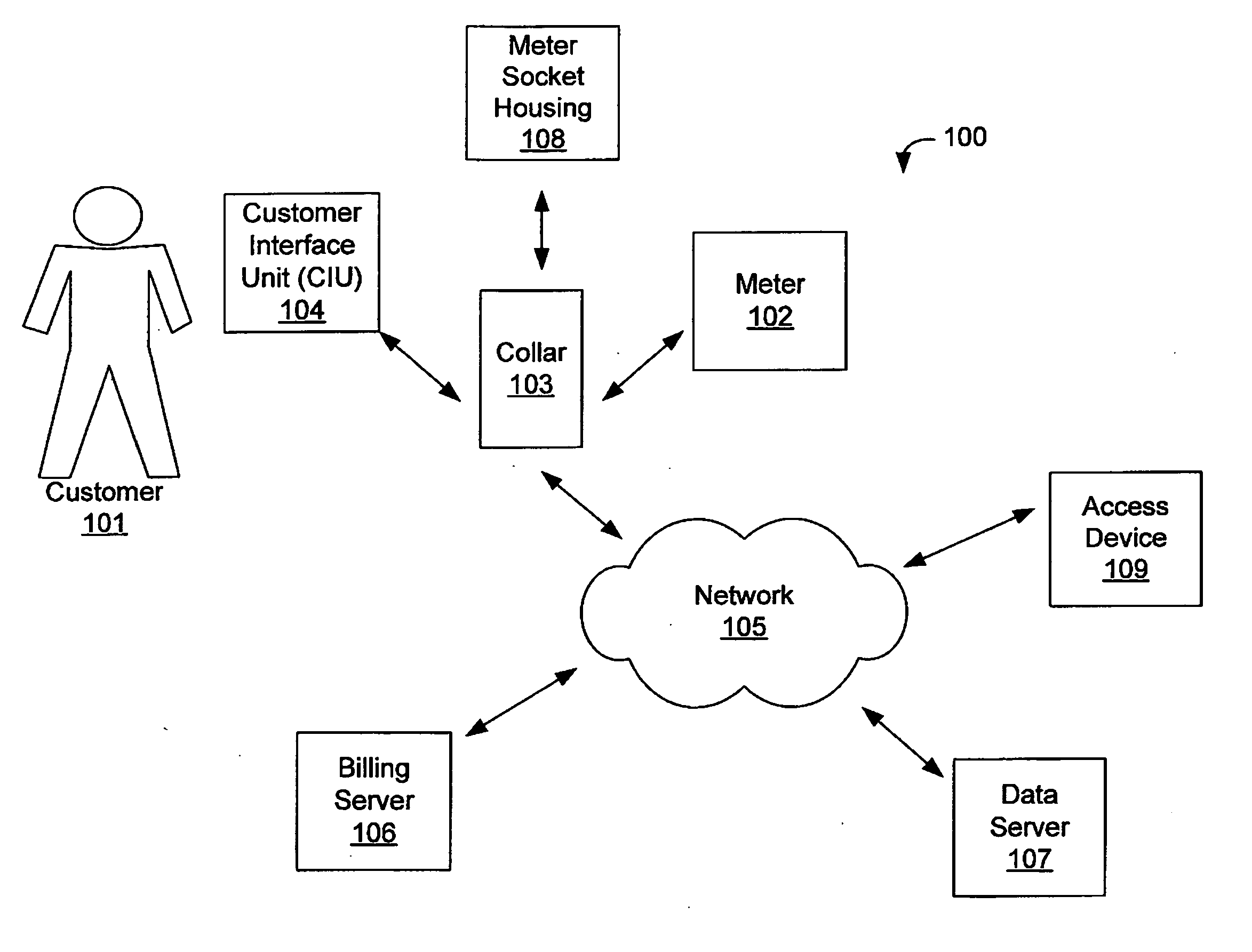
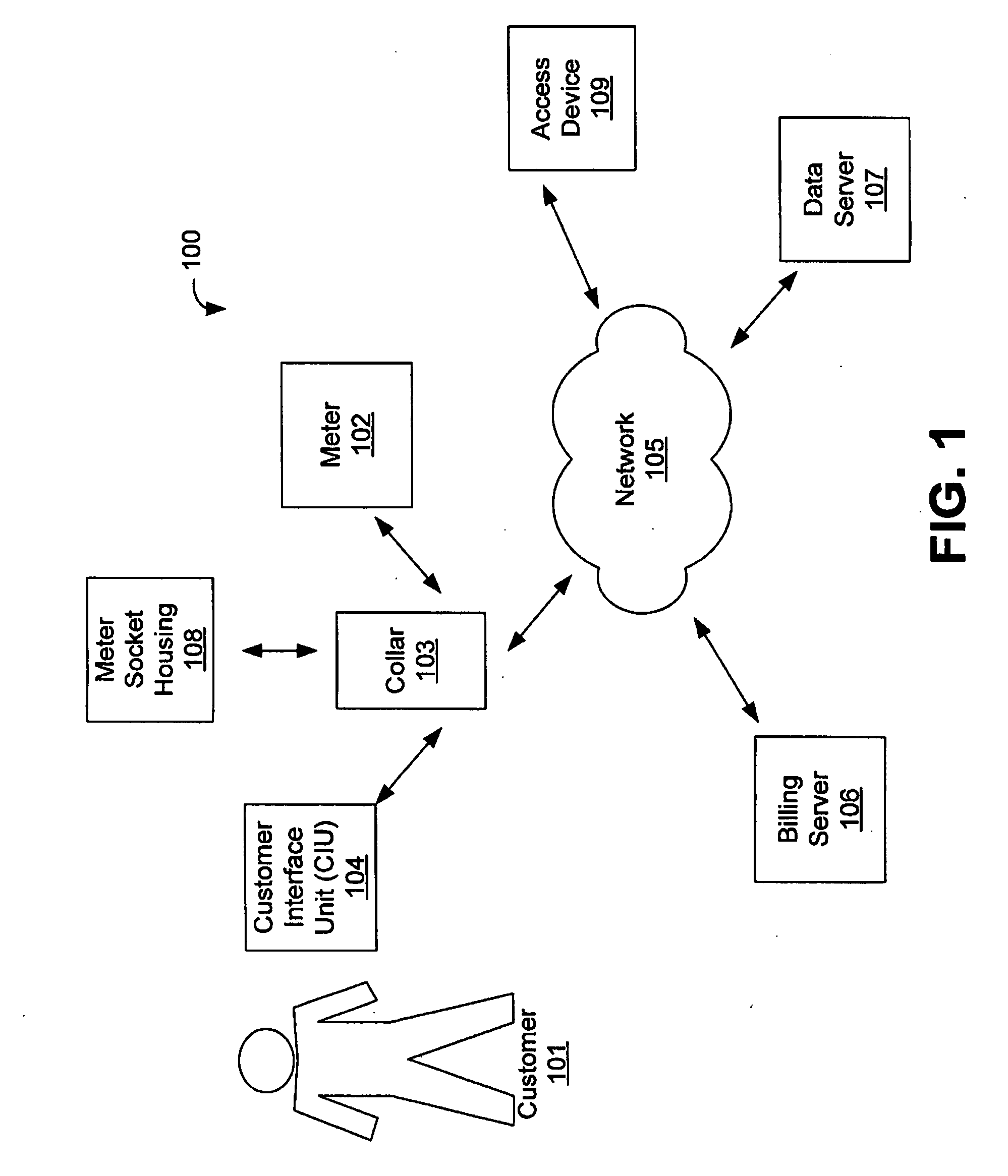
[0025] Embodiments of the present disclosure generally pertain to systems and methods for reading and controlling utility meters. FIG. 1 illustrates a collar-based utility meter control system 100 in accordance with an exemplary embodiment of the present disclosure. The system 100 comprises an adapter collar 103 communicating with a utility meter 102 and a customer interface unit (CIU) 104. Utility meter 102 may be of any type provided by a utility service provider, and in some embodiments is an American National Standards Industry (ANSI) C12 meter. Although this specification primarily describes a power meter, the present invention is also used for gas and water meters. Collar 103 connects between a standard utility meter socket housing 108...


PUM


Abstract

A system and method for monitoring and controlling utility meters is provided. A collar communicatively connected to the utility meter monitors power usage and provides usage data, power quality data, and other data to the utility and the customer. The system provides for pre-pay power, and the collar relay can automatically connect or disconnect power to a customer as required. The system provides intelligent remote control of utility meters via wireless or other communications means.

Description

REFERENCE TO RELATED APPLICATIONS [0001] This application claims priority to Provisional Patent Application U.S. Ser. No. 60 / 817,487, entitled “Ethernet Meter Device” and filed on Jun. 29, 2006, which is fully incorporated herein by reference.FIELD OF THE INVENTION [0002] The invention provides a long range, communication independent, collar-based, device with associated software and firmware, capable of power supply output, electric service disconnect / reconnect, limiting current, metering information, and communicating with and controlling local area network devices for provision of application functions desirable in the utility industry. [0003] Specifically, the invention allows utility service providers the ability to obtain real time metering information via a collar-mounted device that is installed between the existing meter socket and the electric meter. BACKGROUND OF THE INVENTION [0004] Most utility providers measure the usage of energy or gas or water through devices called...

Claims


Application Information

Patent Timeline
IPC IPC(8): G06Q10/00G06F17/10G06F17/30G06F17/40
CPCG01D4/004G06Q20/102G06Q30/04G06Q40/025Y04S20/40Y02B90/242Y04S20/322Y04S20/46Y02B90/245G06Q50/06Y02B90/20Y04S20/30G01D2204/18G06Q40/03
Inventor O'NEIL, ADRIANHARBIN, BENJAMIN
Owner CARINA TECH
Why Eureka
Try Eureka