
Steer wheel control system with stationary piston and reciprocating cylinder

a control system and steering wheel technology, applied in the direction of steering initiation, vehicle components, steering parts, etc., can solve the problems of affecting the entire steering assembly, the transmission of the steer wheel from the roadway, and the excessive fatiguing of city driving, so as to improve the service life reduce the wear of the steer wheel, and be easy to understand

Active Publication Date: 2007-05-22
GLENDALE DEV
View PDF54 Cites 5 Cited by
  • Summary
  • Abstract
  • Description
  • Claims
  • Application Information

AI Technical Summary

Benefits of technology

[0019]The invention provides improved on-center control of the steer wheels, and significantly reduces driver fatigue because it results in a major reduction in driver steering inputs. The invention also eliminates the need for positive caster offset by providing directional stability of steer wheels with no positive caster, i.e., a caster angle of zero degrees (0°). Thus, on-center tracking of the steer wheels is achieved by a means that does not have the deficiencies inherent in positive caster offset and that substantially reduces the need for corrective steering inputs from the vehicle driver.
[0020]The positive on-center feel of such a directionally stable vehicle provides a new level of drivability for motor vehicles, including automobiles, trucks, buses, campers and motorized homes. The invention thus achieves new levels of directional stability and drivability, which reduce driver fatigue to a level that cannot be achieved by conventional positive caster centering. When a driver turns the steering wheel of modern over-the-road vehicles, power steering does the work. If these vehicles utilize the present invention and the steering wheel is released, the centering control system goes to work and makes the steered wheels track straight with great accuracy by counteracting spurious steering inputs as described below.

Problems solved by technology

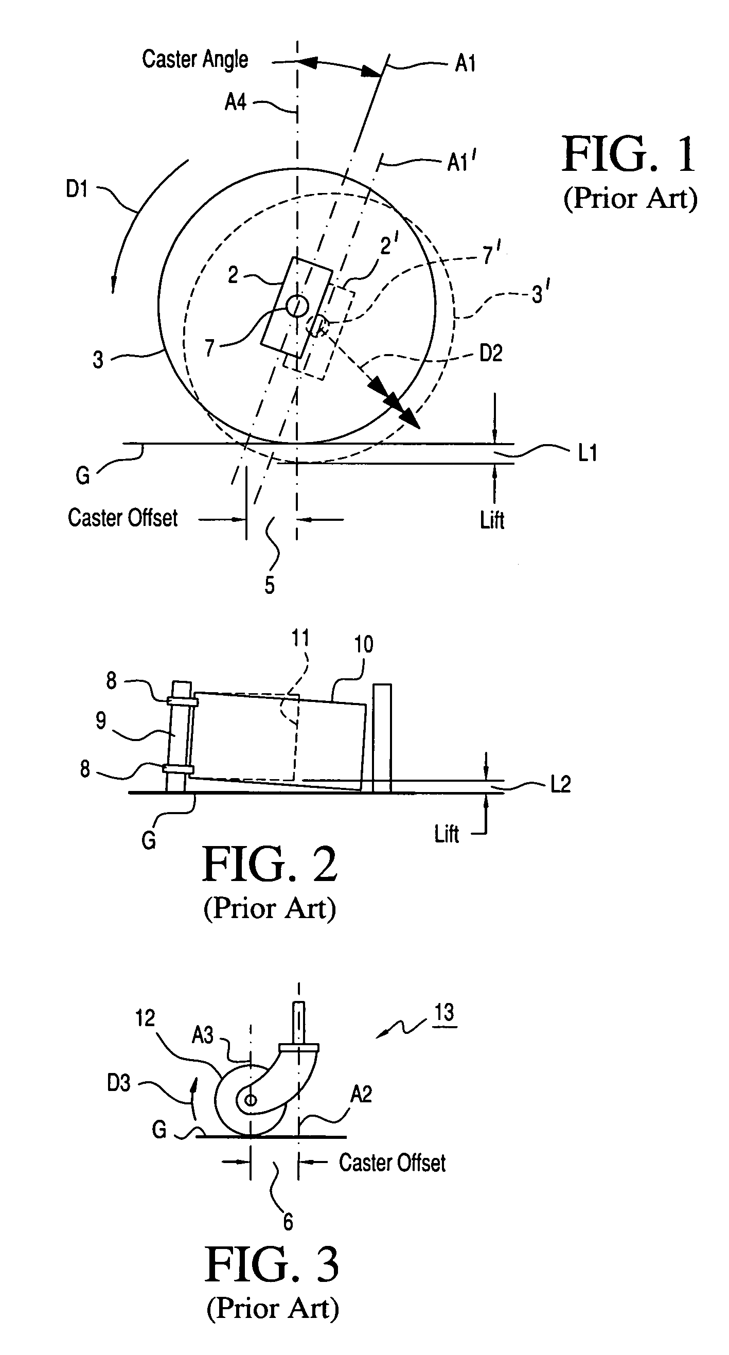
The use of positive king pin angles involves compromises over the full steering spectrum because it results in positive caster offset and thereby produces castering of the steer wheels.
Castered steer wheels also allow steering inputs from rutted and other imperfect roadway surfaces to steer back against the driver and thereby cause road wander, which is a universal driving complaint, particularly by drivers of heavy vehicles such as trucks and motor homes.
In addition, due to increased turning-lift effects, generous positive king pin angles provide significant resistance to small radius turns, which can make city driving quite fatiguing.
These adverse effects are some of the negative aspects of attempting to achieve steering system stability through generous amounts of positive king pin angle.
Another drawback of prior art steering systems is that spurious inputs transmitted from the roadway through the steer wheels affect substantially the entire steering assembly before encountering any stabilizing resistance from the steering wheel.
Such oscillations cause wear and slack in ball joints and other connections and have long been considered a primary source of stress fatigue which can lead to premature failure of various steering system components.
Mechanical slack due to worn parts can also be a cause of steering system oscillations and vehicle wandering that require constant corrections and therefore produce driver fatigue.
Keeping a vehicle tracking straight and under control currently requires an inordinate amount of driver steering corrections to counteract the adverse side effects of castered steer wheels.
The repetitive task of making numerous precise steering corrections mile after mile weighs heavily on a driver's physical and mental well-being, and may result in extreme driving fatigue.
My Precision Steer Wheel Control Technology (PSWCT) has brought to light incorrect technical assumptions that have been responsible for this long-standing major vehicle design oversight, which has in effect been responsible for a lack of heavy vehicle directional stability and related highway safety issues.
For over a half a century, the driving of heavy vehicles that are lacking in directional stability has required an inordinate amount of corrective driver steering to keep the vehicle going straight and under control.
It has been shown that the industry-wide method of slanting the king pins of the steer wheels to achieve steering wheel returnability is the major cause of the unstable behavior of the steer wheels, which results in driver fatigue and a surprising number of other drivability and operational problems.
While this low-cost simple method of achieving steering wheel returnability is desirable from a manufacturing point of view, the resultant operational problems are very undesirable to the consumers, especially to the heavy vehicle drivers who must endure the million upon millions of miles that are many times more fatiguing to drive than they would be in a directionally stable vehicle that is not adversely affected by crosswinds.
Historians will find it hard to rationalize how the hundred-year-old method of achieving steering wheel returnability by the “turning-lift effect” could have been used for so long, without steer wheel castering problems being recognized for their negative effect on heavy vehicle drivability.
It was not for the lack of consumer complaints about the repetitive steering corrections required to maintain directional control in spite of road wander and steering wheel pull, about crosswind driving fatigue, and about the cost of accelerated steer wheel tire wear.
In the beginning when the horseless carriage first took to the road, uncomplicated simple technology was of great importance.
On either side near the gate's closed position, the turning-lift effect diminishes and becomes almost neutral such that its weight alone is not able to hold the gate in the fully closed position, requiring a suitable latch mechanism to keep it fully closed.
In a similar manner to the turning lift of the farm gate, when the steer wheels of a vehicle return toward their lowermost on-center, straight ahead position, the turning-lift effect also diminishes and does not have enough centering force to keep the steer wheels tracking straight in the on-center driving position.
Therefore, the unstable behavior of the steer wheels near the on-center position requires that they be constantly controlled by corrective driver steering input.
The inherent lack of steer wheel directional stability in the on-center driving position is made worse because the same slanted king pin angle that produces the turning-lift effect also produces a steer wheel castering effect that greatly adds to the unstable behavior of the steer wheels during crosswind and crowned road driving conditions.
It is amazing that the adverse effect of steer wheel castering has failed to be better understood over the many years because of an original misleading choice of terms.
Unfounded theories, attempting to explain how the castered wheel functions to make a vehicle directionally stable, have been repeated in various technical publications, greatly adding to the confusion.
Crosswind driving is probably the most exhausting driving experience that heavy vehicle drivers must frequently endure because of the repetitive driver steering corrections required to keep the vehicle under control.
Crosswind driving is therefore one of the major causes of driving fatigue and related heavy vehicle highway safety issues.
During adverse road and wind conditions, the tests also demonstrated that the unstable steer wheel activity increased substantially, requiring a corresponding increase in driver steering inputs to maintain directional control.

Method used


Image

  • Steer wheel control system with stationary piston and reciprocating cylinder
  • Steer wheel control system with stationary piston and reciprocating cylinder
  • Steer wheel control system with stationary piston and reciprocating cylinder

Examples


Embodiment Construction

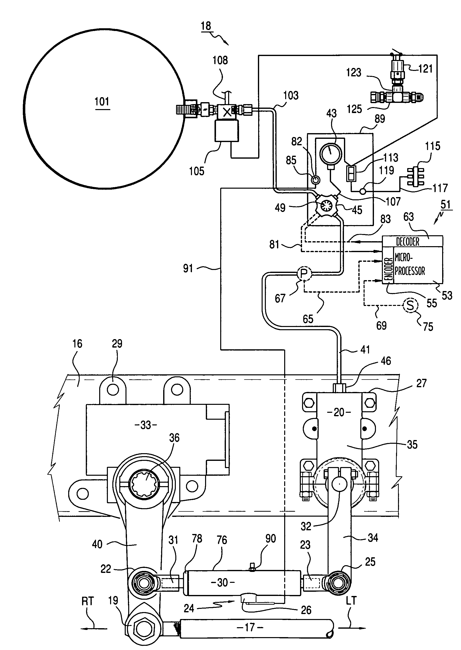
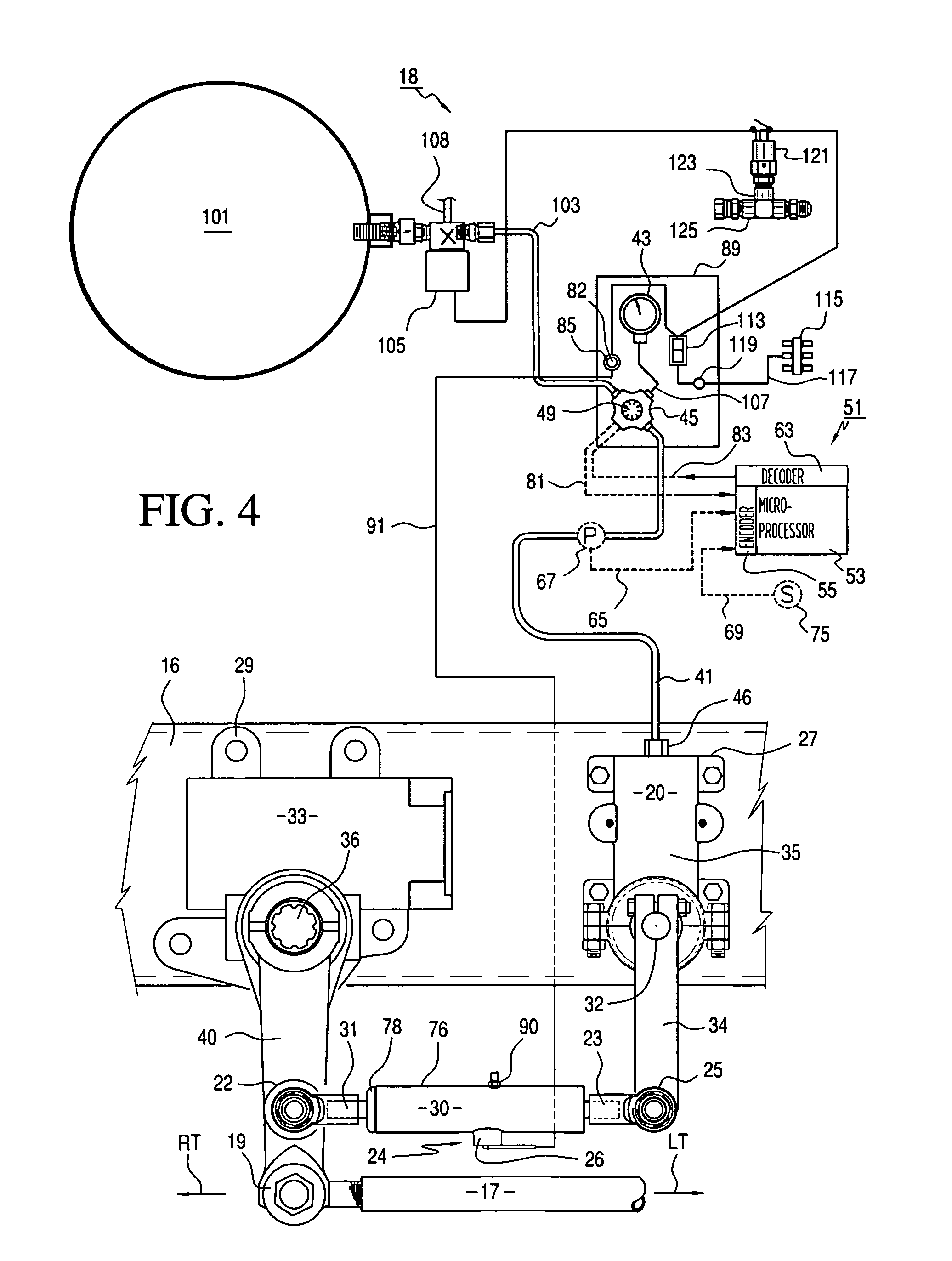
[0069]Referring to FIG. 4 of the drawings, the precision steer wheel control system of the present invention comprises a steer wheel control system, generally designated 18, which includes a centering unit 20 and a trimming unit 30 that form a composite assembly that may be connected between a frame rail 16 and a steering lever or Pitman arm 40 of a conventional motor vehicle. Steering inputs by the driver are transmitted to the vehicle tie rod (not shown) by a drag link 17 and the Pitman arm 40, which pivots in response to a steering shaft 36 of a conventional steering gear within a housing 33. The distal end of a centering lever 34 of centering unit 20 is connected to the Pitman arm 40 by means of the trimming unit 30, which has a cylinder rod23 connected to lever 34 by a ball joint 25 and a trim piston rod 31 connected to the Pitman arm 40 by a ball joint 22. The steering gear housing 33 and a housing 35 of the centering unit 20 are both mounted on the frame rail 16 by bolts that...


PUM


Abstract

A steering system control apparatus having a centering unit for resisting off-center movement of the steer wheels of a vehicle and returning them to a selected center position after each such movement. A centering shaft is connected to the steering shaft of a vehicle steering gear for rotational reciprocation therewith and an intermediate rotational position thereof defines a neutral position that is remotely adjustable by a trimming unit to vary the selected center position of the steering system during vehicle operation. A holding force and a return force are applied to the centering shaft by a pressurized cylinder arranged for reciprocal movement relative to a stationary piston.

Description

FIELD OF THE INVENTION[0001]This invention relates to vehicle steering systems and more particularly to a device for holding the steer wheels of a motor vehicle, such as a motor home, bus, truck, automobile or the like, so that a center steering position is maintained in spite of spurious steering inputs, such as those caused by variable crosswinds, crown curvature or slant of the highway, or other factors tending to adversely affect vehicle steering by the driver.BACKGROUND OF THE INVENTION[0002]The steering systems of highway motor vehicles and the like are designed primarily for driver control. In these systems, the steering force required on the steering wheel and the ratio between steering wheel movement and movement of the steerable ground wheels (also referred to herein as “steer wheels”) depend upon the characteristics of the particular vehicle and the conditions under which it will usually be operated. A wide variety of extraneous forces can act on a vehicle steering system...

Claims


Application Information

Patent Timeline
Patent Type & Authority Patents(United States)
IPC IPC(8): B62D7/22
CPCB62D6/04B62D7/22B63H25/04
Inventor HOWARD, DURRELL U.
Owner GLENDALE DEV
Learn More