Wheel suspension device

a technology of suspension device and wheel, which is applied in the direction of suspension arms, resilient suspensions, pivoted suspension arms, etc., can solve the problems of limited vertical distance the wheel/wheel axle could theoretically move in the vertical direction, and the allowed displacement of the wheel/wheel axle relative to the frame is limited, so as to improve the terrainability of this type of working machine, improve the performance of the vehicle, and improve the effect of performan

Inactive Publication Date: 2017-07-20
VOLVO CONSTR EQUIP
View PDF0 Cites 3 Cited by
  • Summary
  • Abstract
  • Description
  • Claims
  • Application Information

AI Technical Summary

Benefits of technology

[0006]The allowed displacement of the wheel / wheel axle relative to the frame in the vertical direction is however limited due to the presence of other components on the vehicle. The position and width of the dump body relative to the axle track width (distance between a wheel on the left side and a wheel on the right side) of the articulated hauler, will often limit the distance the wheel theoretically could be moved in the vertical direction. The size of the dump body is designed with the aim of fulfilling the demands on load capacity.
[0007]Whilst a conventional bogie solution is robust and has been proven to exhibit good performance, there is still a need of further reducing slip and improving the terrainability of this type of working machines.
[0008]It is desirable to provide a wheel suspension device for a vehicle, by which device the performance of the vehicle can be improved.
[0009]The invention is based, according to an aspect thereof, on the insight that by the provision of a wheel suspension device having a beam connectable to a frame of the vehicle and a wheel spindle for receiving a wheel, the wheel spindle having an axis coinciding with the intended wheel rotation axis, the beam having a pivot axis for pivoting the beam relative to the frame about the pivot axis, the wheel spindle being arranged on the beam for enabling the wheel to move up and down relative to the frame by means of pivot motion of the beam, and wherein the beam pivot axis and the wheel spindle axis are angled relative to each other, the wheel suspension device can be installed such that beam pivot axis is angled relative to a horizontal plane while the wheel spindle axis being substantially horizontal. Thereby, when the wheel is moved upwardly by pivoting the beam relative to the frame, an outward lateral movement of the wheel can be obtained, and thus the allowed vertical displacement of the wheel can be increased without interfering with other vehicle parts. Such an increased vertical wheel travel distance will prevent slip and improve the terminability of the vehicle.
[0010]According to one embodiment of the wheel suspension device, the beam and the wheel spindle are pivotally connected to each other for pivoting relative to each other about a further pivot axis. Preferably, the further pivot axis is substantially in parallel with the beam pivot axis and displaced relative to the beam pivot axis. Hereby, the wheel can be steered by pivoting the wheel spindle relative to the beam about the further pivot axis. This in turn will decrease the tire wear and improve terrainability and manoeuvring of the vehicle. The pivot motion about the further pivot axis can be performed by a motor, such as a hydraulic or electric motor, or by one or more hydraulic cylinders, and any other auxiliary equipment such as gears, levers, etc.
[0011]Furthermore, by pivoting the wheel spindle relative to the beam, it is also possible to adjust for the tilt angle of the wheel that arises due to the fact that the wheel has been pivoted relative to the frame about the angled beam pivot axis. In other words; when the wheel is moved upwards and thereby also in the lateral direction, a tilt angle of the vehicle can be prevented or at least counteracted by pivoting the wheel spindle relative to the beam about the further pivot axis.

Problems solved by technology

The allowed displacement of the wheel / wheel axle relative to the frame in the vertical direction is however limited due to the presence of other components on the vehicle.
The position and width of the dump body relative to the axle track width (distance between a wheel on the left side and a wheel on the right side) of the articulated hauler, will often limit the distance the wheel theoretically could be moved in the vertical direction.

Method used


Image

  • Wheel suspension device
  • Wheel suspension device
  • Wheel suspension device

Examples


Embodiment Construction

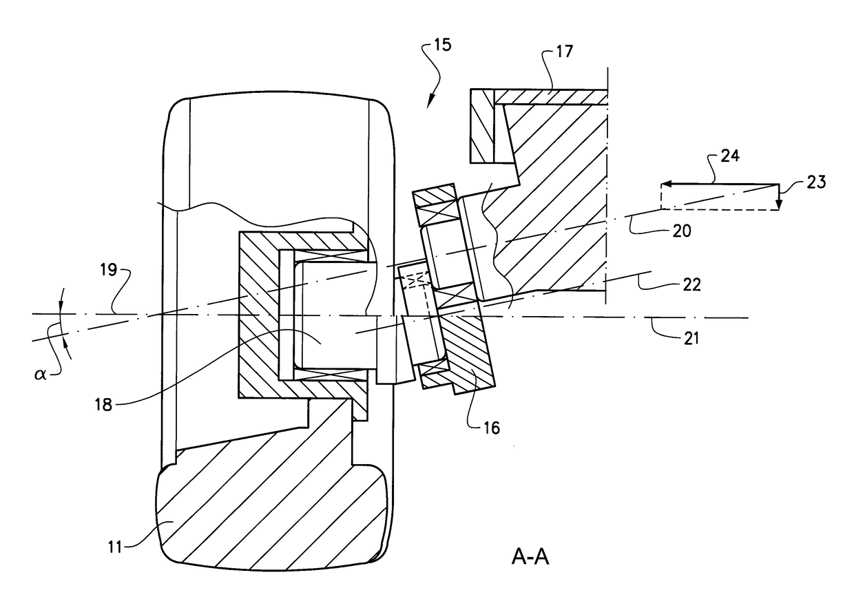
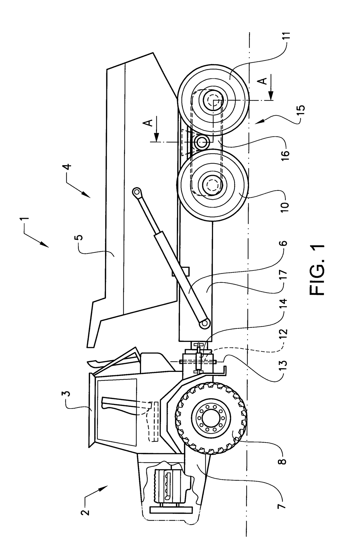
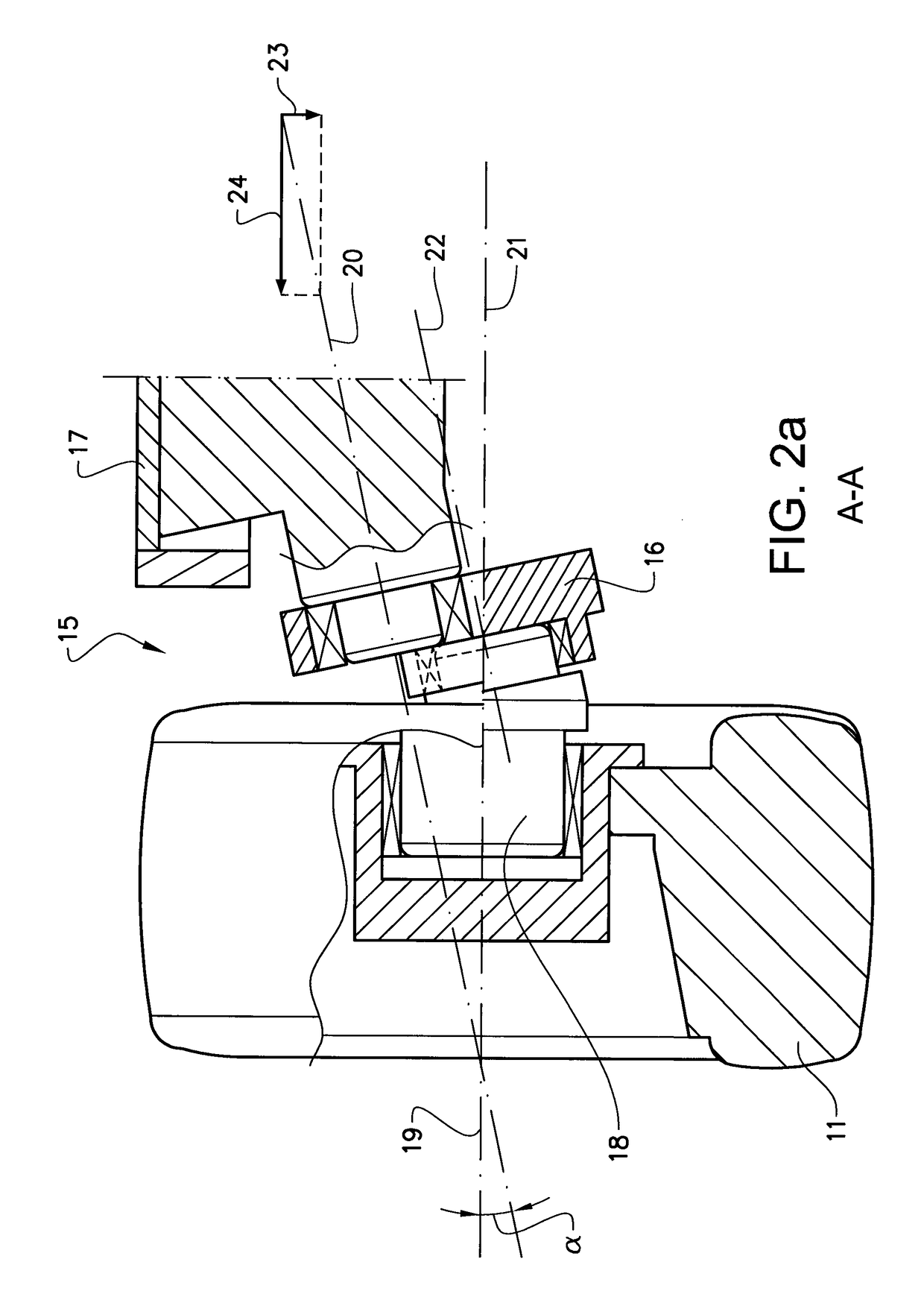
[0023]FIG. 1 is an illustration of a vehicle 1 according to the invention. The articulated hauler illustrated is an example of a working tnachine where the invention can be applied. The articulated hauler has a front section 2 with a cab 3 for a driver and a rear section 4 with a platform having a dump body 5 or container arranged thereon for receiving load. The dump body 5 is preferably pivotally connected to the rear section and tiltable by means of a pair of tilting cylinders 6, for example hydraulic cylinders. The front section has a front frame 7 and a pair of wheels 8 suspended from the front frame 7. The rear section 4 has a rear flume 17 and two pair of wheels 10, 11 suspended from the rear frame 17. The working machine is frame-steered, i.e. there is a pivot joint 12 connecting the front section 2 and the rear section 4 of the working machine 1. The front section and the rear section are pivotally connected to each other for pivoting about a substantially vertical pivot axi...


PUM


Abstract

A wheel suspension device for a vehicle includes a beam connectable to a frame of the vehicle and a wheel spindle for receiving a wheel, wherein the wheel spindle has an axis coinciding with the intended wheel rotation axis, and the beam has a pivot axis for pivoting the beam relative to the frame about the pivot axis. The wheel spindle is arranged on the beam for enabling the wheel to move up and down relative to the frame by pivot motion of the beam and the beam pivot axis and the wheel spindle axis are angled relative to each other.

Description

BACKGROUND AND SUMMARY[0001]The invention relates to a wheel suspension device for a vehicle having a frame, where the wheel is allowed to move up and down relative to the frame by means of pivot motion.[0002]The invention can be applied on different types of vehicle, in particular working machines such as articulated haulers.[0003]Although the invention will be described with respect to a wheel suspension device for an articulated hauler, the application of the invention is not restricted to this particular application, but may also be used in other vehicles, for instance other types of work machine such as a wheel loader, a dump truck or any other type of construction equipment.[0004]A working machine is usually provided with a bucket, container or other type of implement for digging, lifting, carrying and / or transporting a load.[0005]For example, an articulated hauler has a dump body for transporting a load. This type of working machine has also a bogie for suspension of the rear...

Claims


Application Information

Patent Timeline
Patent Type & Authority Applications(United States)
IPC IPC(8): B60G5/02B60G7/02B60G3/14
CPCB60G5/02B60G13/08B60G7/02B60G3/145B60G2200/132B60G2200/40B60G2300/02B60G2300/09B60P1/18
Inventor PETTERSSON, HENRICSODERBERG, TOBIASQAADOUN, AMIN
Owner VOLVO CONSTR EQUIP
Why Eureka
Try Eureka