Essence bottle wick
- Summary
- Abstract
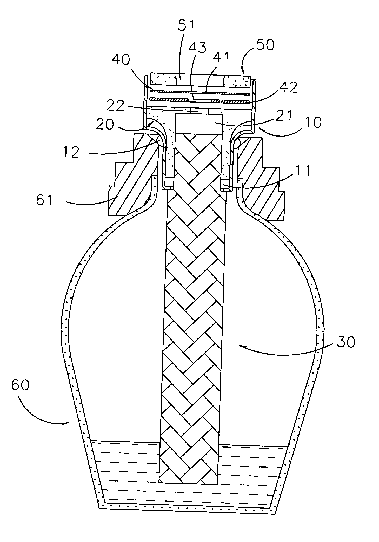
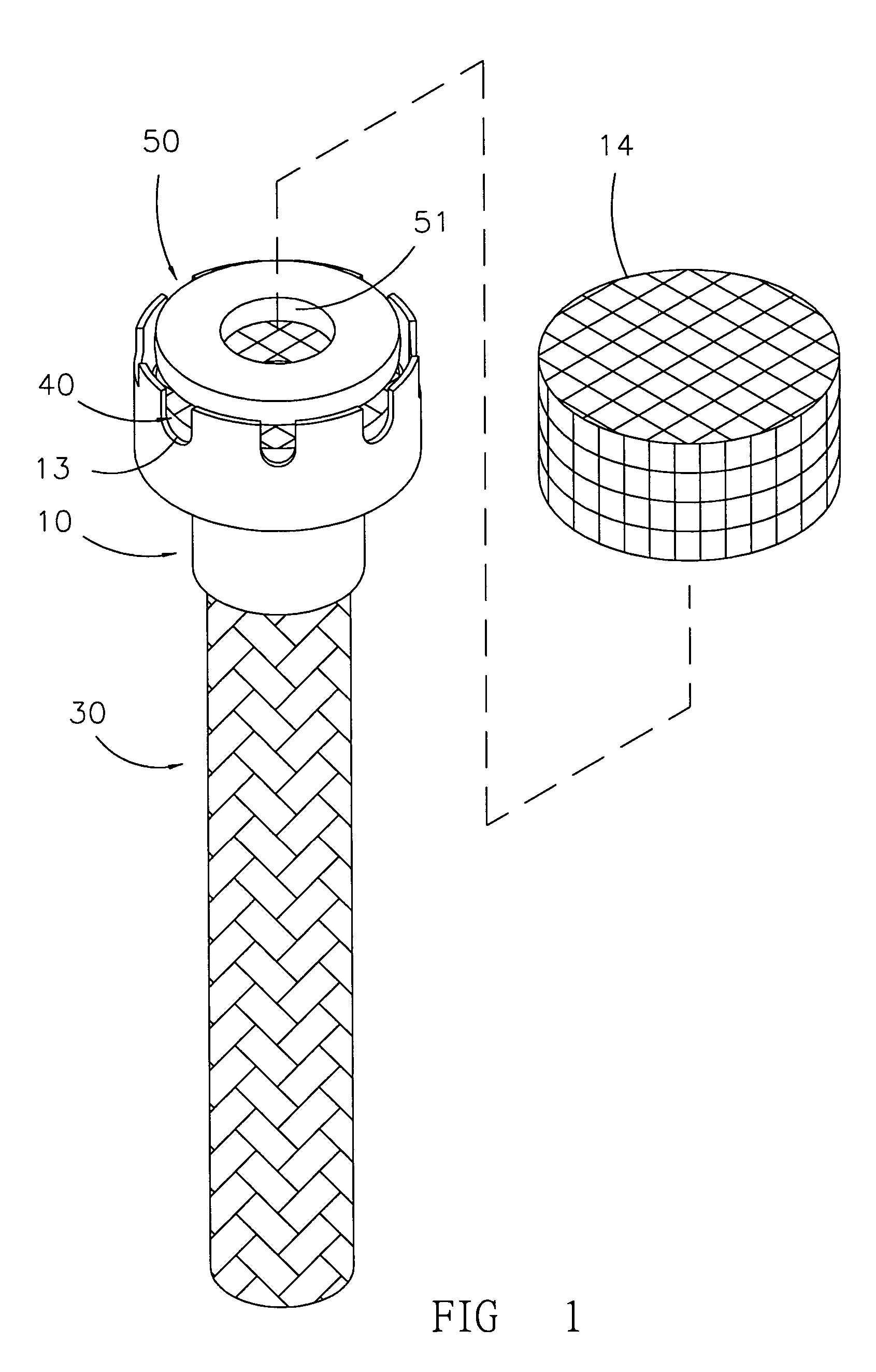
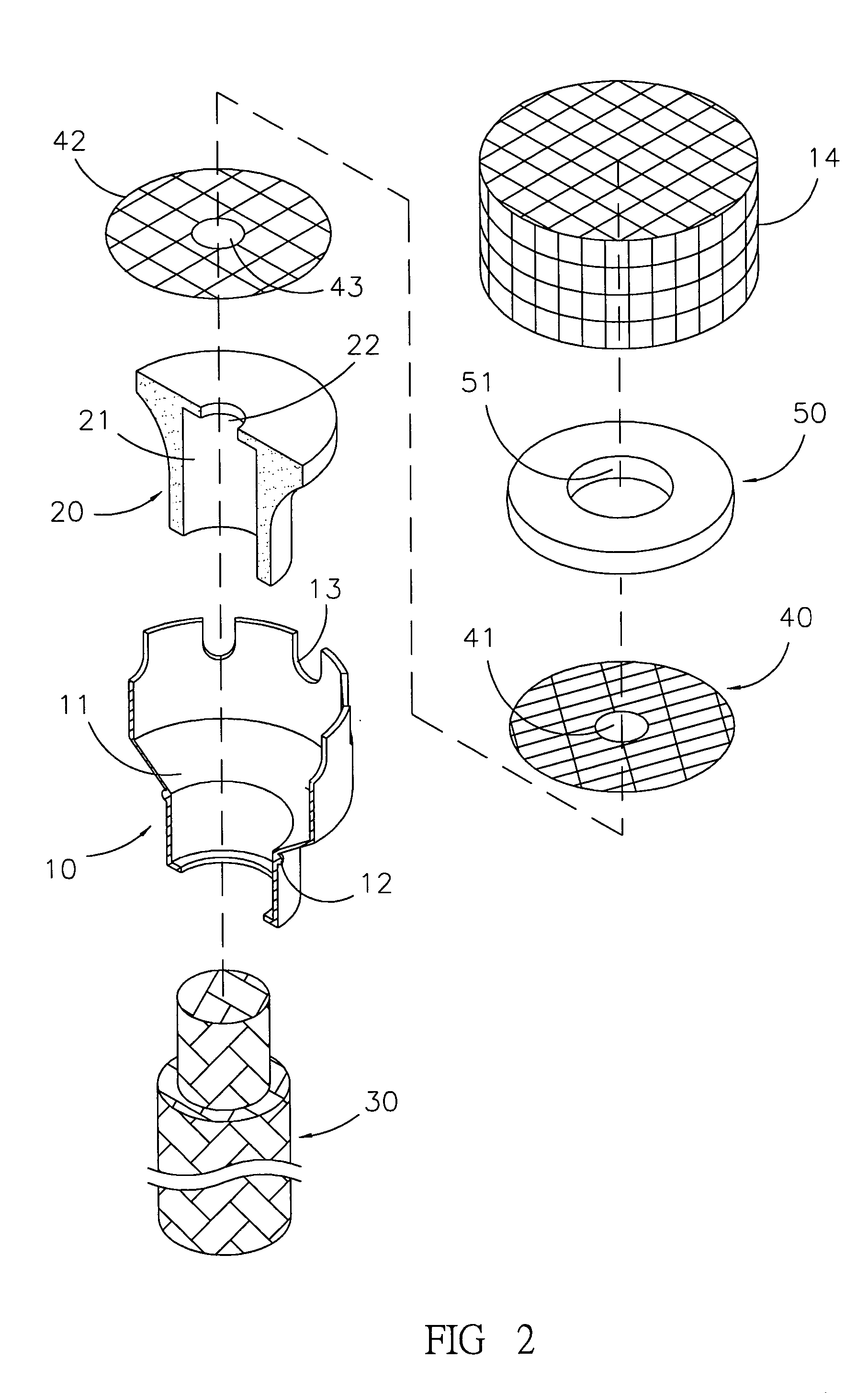
- Description
- Claims
- Application Information
AI Technical Summary
Benefits of technology
Problems solved by technology
Method used
Image

Examples
second embodiment
[0031] Referring to FIG. 5, in the present invention, the base 10 on the upper edge thereof carries a plurality of fixing elements 14a, which are shaped like strips and are slightly bent inwards, holding the separating grid 40 and the catalyst 50 in fixed positions on the heat-resistant element 20.
third embodiment
[0032] Referring to FIG. 6, in a third embodiment the present invention has a separating grid 40a, a catalyst 50a, and a positioning cap 14a. The separating grid 40a has an outer peripheral grid 44a, protecting the catalyst 50a from shock and resulting damage and allowing to fasten the positioning cap 14a on the catalyst 50a with ease.
fourth embodiment
[0033] Referring to FIG. 7, in a fourth embodiment the present invention has a heat resistant element 20b with a central hole 22b, a catalyst 50b with a central hole 51b, and a separating grid 40b with a peripheral grid 44b and an enlarged central hole 41b surrounded by an inner peripheral grid 45b. The heat resistant element 20b carries a projection 23b, which reaches into the central hole 45b. The central hole 45b has an outer diameter that is slightly smaller than the inner diamater of the central hole 51b of the catalyst 50b, allowing easy installation within the central hole 51b. While essence is burned, the projection 23b of the heat resistant element 20b has a temperature that is lower than the temperature of the catalyst 50b, so that vaporized essence emanating from the central hole 22b of the heat resistant element 20b will not easily be damaged.
[0034] While the invention has been described with reference to preferred embodiments thereof, it is to be understood that modific...
PUM
 Abstract
Description
Claims
Application Information
 - Generate Ideas
- Intellectual Property
- Life Sciences
- Materials
- Tech Scout
- Unparalleled Data Quality
- Higher Quality Content
- 60% Fewer Hallucinations
Browse by: Latest US Patents, China's latest patents, Technical Efficacy Thesaurus, Application Domain, Technology Topic, Popular Technical Reports.
© 2025 PatSnap. All rights reserved.Legal|Privacy policy|Modern Slavery Act Transparency Statement|Sitemap|About US| Contact US: help@patsnap.com