Insulated panel and glazing system comprising the same

a technology of insulated panels and glazing systems, applied in the direction of thin material processing, construction, building components, etc., can solve the problems of increasing the cost of maintaining the climate within the building at a level, and affecting the insulating effect of the building

Inactive Publication Date: 2005-04-07
CABOT CORP
View PDF32 Cites 63 Cited by
  • Summary
  • Abstract
  • Description
  • Claims
  • Application Information

AI Technical Summary

Benefits of technology

[0008] The invention further provides a glazing panel, preferably translucent, comprising: (a) a thermoplastic panel comprising (i) a first thermoplastic sheet, (ii) a second thermoplastic sheet, and (iii) two or more supporting members, the supporting members being disposed between the first and second thermoplastic sheets, and the supporting members defining at least one channel disposed between the first and second thermoplastic sheets, the channel having an internal volume, and (b) hydrophobic aerogel particles, the hydrophobic aerogel particles being disposed within the channel.

Problems solved by technology

While the use of such glazing materials can dramatically improve the quality of indoor lighting, buildings incorporating relatively large amounts of such glazing materials often are poorly insulated.
Therefore, the overall thermal transmission of a building incorporating relatively large amounts of such glazing materials typically is significantly higher than a similar structure using less of the same, and such buildings often experience relatively large amounts of heat flux across the glazing materials, which can dramatically increase the cost of maintaining the climate within the building at a level considered comfortable by the occupants.
While such multiwall panels do exhibit improved (i.e., lower) thermal transmission than conventional, single-pane glazing materials, condensation often forms within the chambers as the panels are exposed to differences in temperature and / or humidity across the major surfaces of the panel.
Furthermore, the structure of the multiwall panels often causes the panel to unevenly refract visible light, which can negatively impact the indoor lighting quality of a structure incorporating the panels as a glazing material.
However, the costs saved due to the improved thermal transmission of the glazing system can often be partially offset by the relatively high labor costs associated with the installation of such insulating panels.
For instance, the insulating panels are extremely fragile and frequently break during the installation due to their relatively large dimensions (e.g., up to about 6 meters or more in length).
The debris generated by such breakage (e.g., glass fibers) can create an environmental hazard for the workers installing the insulating panels and must be painstakingly removed.
In such a configuration, the insulating panel impedes the drainage of condensation that forms on the glass element to which the panel is adhered.

Method used


Image

  • Insulated panel and glazing system comprising the same
  • Insulated panel and glazing system comprising the same
  • Insulated panel and glazing system comprising the same

Examples


example 1

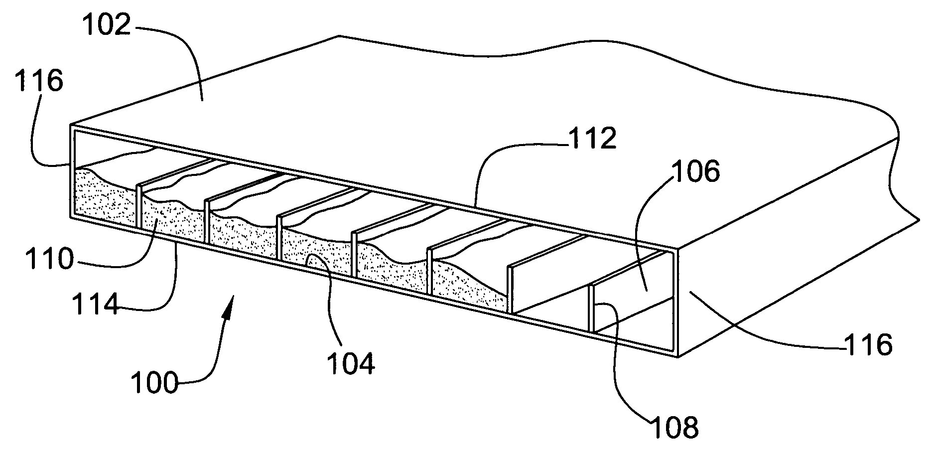
[0054] This example demonstrates the improved U value (i.e., lower thermal transmission) exhibited by a glazing panel according to the invention relative to other glazing panels that do not comprise hydrophobic aerogel particles. The corrected U values for eleven similar translucent glazing panels were measured. Each of the glazing panels comprised a first polycarbonate sheet, a second polycarbonate sheet, and a plurality of supporting members disposed between the first and second polycarbonate sheets to define a plurality of channels between the first and second polycarbonate sheets.

[0055] Glazing Panels 1A (comparative) and 1B (invention) measured approximately 10 mm in thickness, and Glazing Panel 1B (invention) comprised hydrophobic aerogel particles disposed within the channels of the panel.

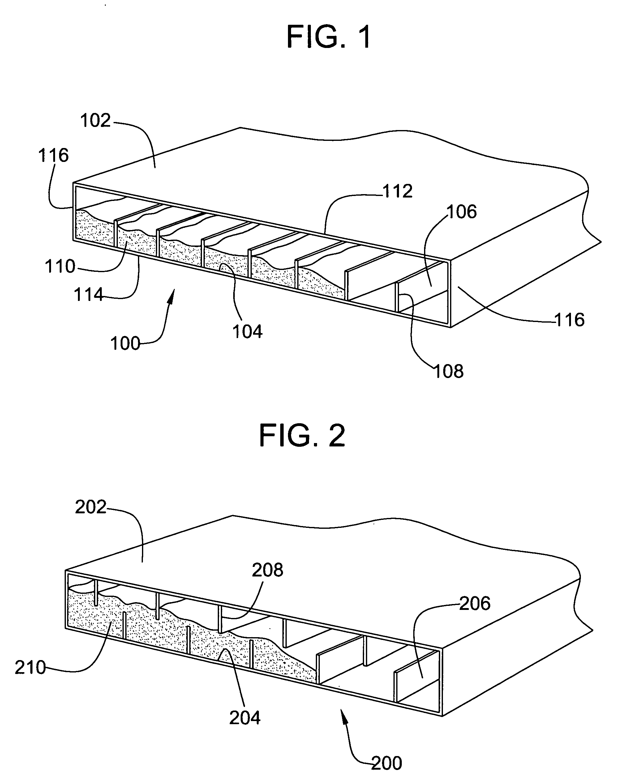
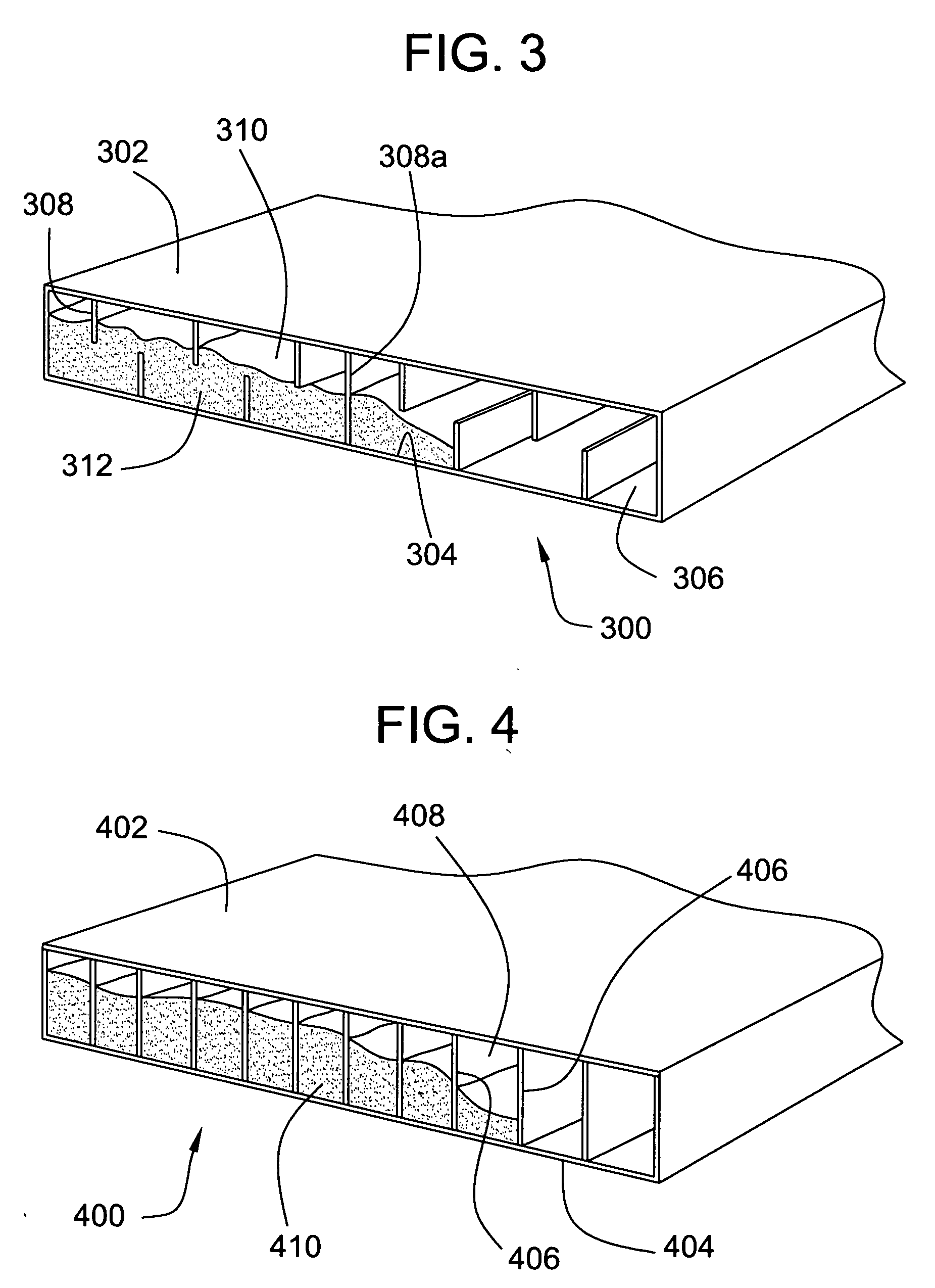
[0056] Glazing Panels 1C-1E measured approximately 16 mm in thickness and further comprised a third polycarbonate sheet disposed between and parallel to the first and second polycarbonate ...

example 2

[0061] This example demonstrates the improved light diffusing properties (i.e., higher haze value) exhibited by a glazing panel according to the invention relative to other glazing panels that do not comprise hydrophobic aerogel particles. Six similar translucent glazing panels (Glazing Panels 2A-2F) were measured to determine the haze value of each panel. Each of the glazing panels comprised a first polycarbonate sheet, a second polycarbonate sheet, and a plurality of supporting members disposed between the first and second polycarbonate sheets to define a plurality of channels between the first and second polycarbonate sheets. Glazing Panels 2A (comparative) and 2D (invention) measured approximately 6 mm in thickness, Glazing Panels 2B (comparative) and 2E (invention) measured approximately 10 mm in thickness, and Glazing Panels 2C (comparative) and 2F (invention) measured approximately 20 mm in thickness. The channels of Glazing Panels 2D-2F (invention) were filled with hydrophob...

example 3

[0064] This example demonstrates the improved U value (i.e., lower thermal transmission) of a glazing system according to the invention relative to other glazing systems. The U values for four similar glazing systems were measured. Each of the four glazing systems (Glazing Systems 3A-3D) was constructed using two similar U-shaped glass elements. The glass elements comprised a base, which measured approximately 262 mm in length, and two legs perpendicularly extending from the base, which legs measured approximately 60 mm in length. The glass from which each element was constructed was approximately 7 mm thick. In order to prevent contact between the legs of one element and the inside surface of the base of the other element, a polymeric gasket was placed on the distal end of each leg. The two U-shaped glass elements were arranged so that the legs of each glass element projected from the base of the glass element toward the base of the other glass element, thereby defining a cavity be...


PUM


Abstract

The invention provides a translucent glazing panel comprising: (a) a thermoplastic panel comprising (i) an outer wall having an inner surface defining an internal channel, the internal channel having an internal volume, and (ii) at least one inner wall protruding from the inner surface into the internal channel, and (b) hydrophobic aerogel particles, the hydrophobic aerogel particles being disposed within the channel. The invention also provides an insulated glazing system comprising: (a) a first U-shaped element, (b) a second U-shaped element, the first and second elements being disposed to define a cavity therebetween, and (c) an insulating panel disposed within the cavity. The insulated glazing system can further comprise hydrophobic aerogel particles disposed within the internal channel of the insulating panel. The insulating panel of the glazing system also can be the same as the translucent glazing panel described herein.

Description

FIELD OF THE INVENTION [0001] This invention pertains to insulated panels and glazing systems comprising the same. BACKGROUND OF THE INVENTION [0002] In an effort to improve indoor lighting conditions and the aesthetic appeal of enclosed spaces, architects and builders have begun to construct buildings using an increasing large amount of glazing materials and systems, such as windows, skylights, and transparent or translucent walls and roofs. While the use of such glazing materials can dramatically improve the quality of indoor lighting, buildings incorporating relatively large amounts of such glazing materials often are poorly insulated. More specifically, the thermal transmission of conventional glazing materials typically is significantly higher than the thermal transmission of conventional building materials or structures, such as framed roofs and walls. Therefore, the overall thermal transmission of a building incorporating relatively large amounts of such glazing materials typ...

Claims


Application Information

Patent Timeline
Patent Type & Authority Applications(United States)
IPC IPC(8): E04C2/54
CPCE04C2/54Y10T428/24661Y10T428/234Y10T428/239
Inventor ROUANET, STEPHANE F.LITRUN, JAMES N.
Owner CABOT CORP
Why Eureka
Try Eureka