Clock generator module

a generator module and clock technology, applied in the direction of generating/distributing signals, instruments, power supplies for data processing, etc., can solve the problems of poor frequency resolution, low manufacturing cost, and limited functionality of oscillations, and achieve low manufacturing and design cost, less product management, and low cost

Active Publication Date: 2005-04-07
ADLINK TECH INC
View PDF13 Cites 26 Cited by
  • Summary
  • Abstract
  • Description
  • Claims
  • Application Information

AI Technical Summary

Benefits of technology

[0012] According to an aspect of the present invention, the clock generator module is electrically connected with a mainboard through a connector for communicating with each other, wherein the clock generator module communicates with a control logic circuit on the mainboard to generate a required clock frequency. Accordingly, based on the various appliances, a most suitable clock generator module is provided for supplying multiple clock frequency functionality. Thus, the clock generator module of the present invention satisfies every kind of appliance of clock requirements incurring less product management, low manufacture and design cost.

Problems solved by technology

This method of setting up various frequency results in a poor frequency resolution, but however the manufacturing cost thereof is very low.
Further, the functionality of the oscillation is limited to a certain range and is also of accuracy concern.
But the disadvantage is the high manufacturing cost and the highly complicated manufacturing process for producing a DDS IC.
The PLL locks up the clock signal at a certain frequency and result in an absolute accuracy, however generally speaking, the clock resolution is poorer and the clock vibration levels are related to the PLL IC as well.
If an user needs all the three types of clock generators, the user needs to purchase three measuring devices with different types of clock generators, and accordingly, the product management, the cost of design and the production would be expensive.

Method used


Image

  • Clock generator module
  • Clock generator module
  • Clock generator module

Examples


Embodiment Construction

[0018] Reference will be made in detail to the preferred embodiments of the invention, examples of which are illustrated in the accompanying drawings. Wherever possible, the same reference numbers are used in the drawings and the description to refer to the same or like parts.

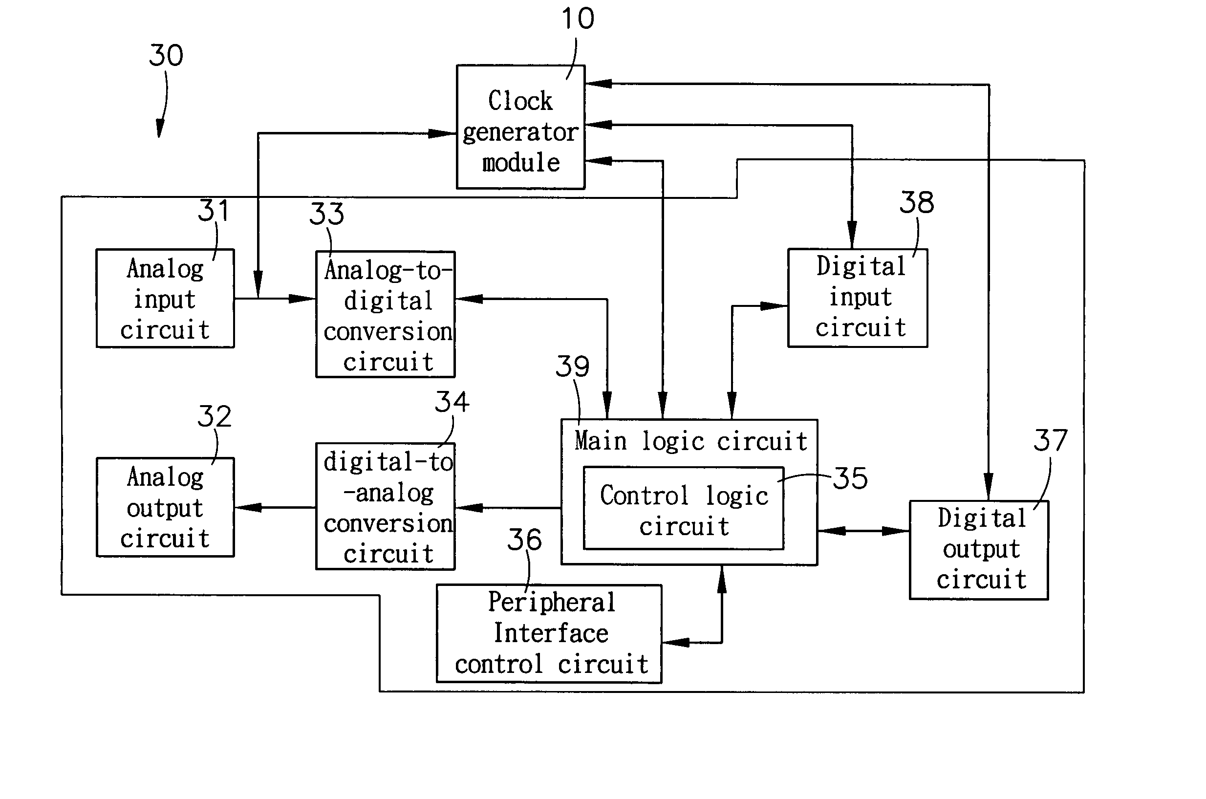
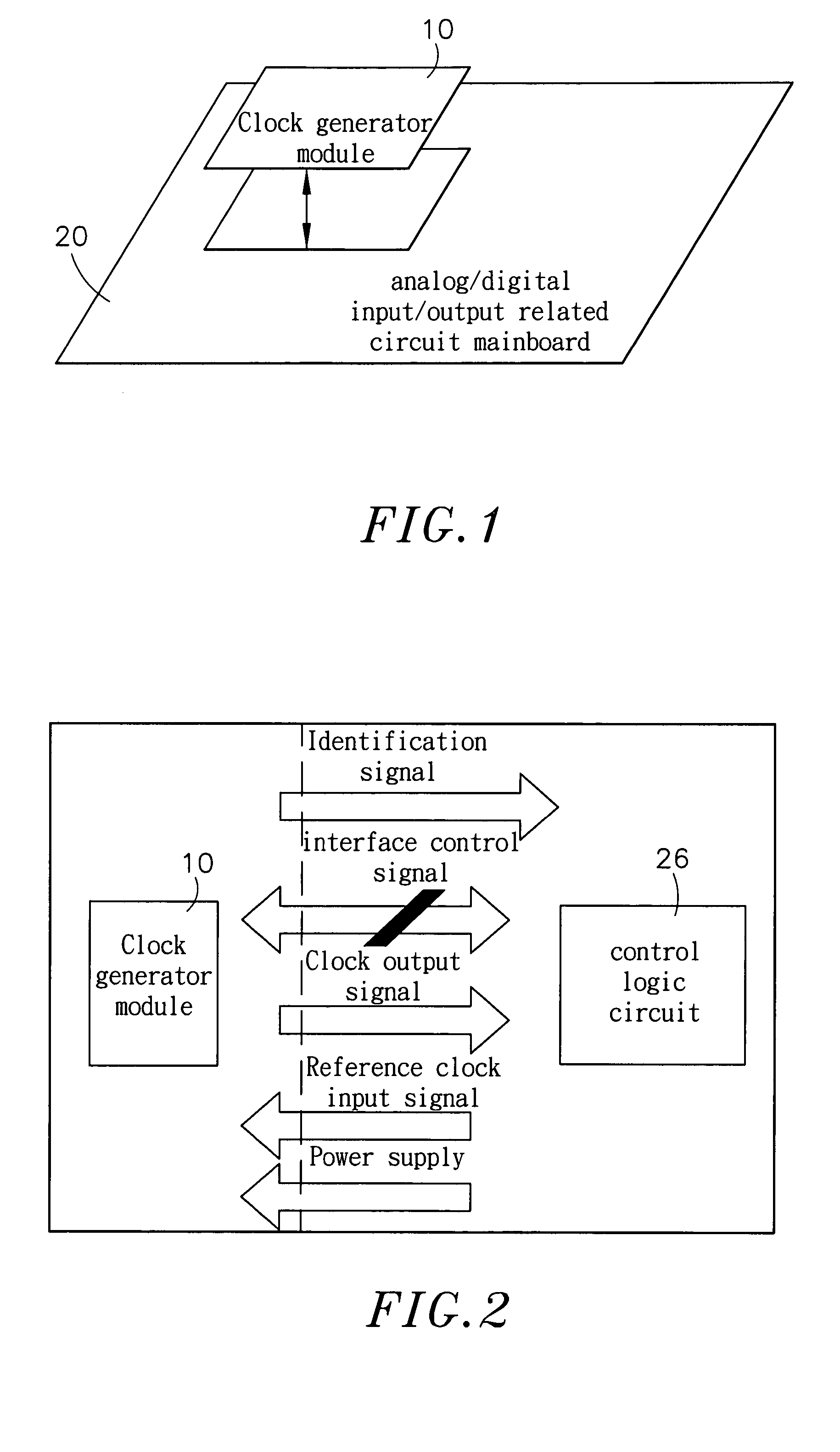
[0019] Referring to FIG. 1, is a block diagram illustrating a linking between the clock generator module and mainboard according to one preferred embodiment of the present invention. As shown in FIG. 1, the clock generator module 10 and the mainboard 20 having an analog or a digital input / output related circuit are electrically connected through a board-to-board connector or a connection wire for communicating with each other through mutual signal transmission. Thus, each related circuit of the mainboard 20 can get the clock frequency in various specifications.

[0020] Referring to FIGS. 1 and 2, respectively illustrate the link between the clock generator module 10 and mainboard 20, and a block diagram of the ...


PUM


Abstract

A clock generator module is disclosed. A clock generator module, electrically connected with a mainboard through a connector for communicating with each other, wherein an interface definition of the clock generator communicates with a control logic circuit of the mainboard to generate a required clock frequency.

Description

BACKGROUND OF THE INVENTION [0001] 1. The Field of the Invention [0002] The present invention relates to a clock generator module, and more particularly relates to a modular clock generator circuit providing various clock frequencies required. Thus, one particular electronic product is extendable for satisfying various frequencies requirements without incurring high cost on product design, and manufacturing and product management. [0003] 2. Description of the Related Art [0004] The available measuring devices, data acquisition device or equipment, comprise a clock generator circuit for either analog input / output functions or digital input / output functions to achieve various functionalities. The clock in an analog input / output circuit is used for providing a sampling or updating clock to an analog-to-digital converter or a digital-to-analog converter integrated circuit. And to use the clock signal in the digital input / output circuit is for digital signal sampling or renewing [0005] T...

Claims


Application Information

Patent Timeline
Patent Type & Authority Applications(United States)
IPC IPC(8): G06F1/08
CPCG06F1/08
Inventor WAN, SHIH-HAOLEE, CHUNG-YI
Owner ADLINK TECH INC
Why Eureka
Try Eureka