Material mover having a fluid film reservoir

a material mover and fluid film technology, applied in the direction of wheelchair/patient conveyance, load securing, transportation items, etc., can solve the problems of patients who cannot by themselves sit up or move, it is difficult to move easily and practically an object, and the range of applications desiring an improved transportation device is vast, so as to facilitate keeping the patient centered, enhance safety, and widen the effect of width

Inactive Publication Date: 2005-04-14
GRAY TEK
View PDF3 Cites 36 Cited by
  • Summary
  • Abstract
  • Description
  • Claims
  • Application Information

AI Technical Summary

Benefits of technology

[0015] In accordance with one embodiment of the present invention, a material mover includes a plenum chamber, which is divided into a plurality of smaller, open-ended chambers through the use of partition members, defined by substantially rectangular top and bottom sheets, and perimeter side walls connecting the top and bottom sheets. Easy, safe and efficient movement of a load placed upon the material mover is achieved by controlling the dispersion of a fluid film formed under the material mover, which is formed by fluid exiting from a plurality of orifices in the bottom sheet. Specifically, a fluid film weir is provided along the bottom periphery of the material mover to inhibit the escape of the fluid film from underneath the material mover. The fluid film weir effectively defines a fluid reservoir under the material mover for maintaining the position of the fluid film and preventing the fluid from randomly and easily escaping from underneath the material mover. Accordingly, by maintaining and controlling a sufficient fluid film beneath a portion of the material mover, substantially less manual effort and electric power is required to move the load.
[0032] Providing orifices in the top sheet of the fluid mattress suppresses decubitis ulcer formation because a fluid film exists between the patient and the upper surface of the fluid mattress. Accordingly, the fluid film lessens the severity of damage occurring at pressure areas on the patient's body, which often occur on bony prominences and cause, for example, sacral decubitus.

Problems solved by technology

From industrial to medical settings, it is often extremely difficult to easily and practically move an object, even with the aid of a transfer device to assist in the transport.
The range of applications desiring an improved transport device is vast.
Patients who cannot by themselves sit up or move can be particularly difficult to move from a stretcher to a bed or vice versa, and repositioning such patients frequently requires two or three nurses, orderlies or other attendants.
A serious drawback of such prior art inflatable transfer devices is that there is no way of controlling the air which exits perforations in the bottom of the transfer apparatus.
As such, the air blowers used to inflate these types of inflatable transfer structures tend to inefficiently consume relatively large amounts of electric power during use, because no attempt has been made to control or inhibit the random dispersion of the air film expelled from underneath the bottom portion of the transfer apparatus.
Consequently, the '291 patent provides no structure that actually controls the rate of air film dispersion from underneath the transfer apparatus, and thus, increased operating costs result from the higher demand for electric power, which is needed to operate the air blower used to drive the transfer apparatus and to counter-balance the high and steady rate of air film dissipation from underneath the transfer apparatus.
In addition to the lack of control over the fluid film randomly expelled from the plenum chamber, prior art inflatable transfer apparatuses are plagued by plenum chamber air loss due to the effects of certain types of stresses, such as stress from maintaining the plenum chamber in an inflated state or vertical or lateral pulling stresses, being placed on the stitched seam lines, which connect the various sheets of the transfer device. FIG. 9 illustrates such a prior art seam line structure in which portions of top sheet 100 and bottom sheet 200 are folded under to form a double layer of top and bottom sheets 100 and 200, respectively, and the double layers are placed parallel to one another and stitched to form the seam line junction.
Air loss from the plenum chamber through such separations or gaps in the seam lines yields an even more inefficient transfer apparatus due to even a higher level of electric power required by the blower unit to maintain an inflated plenum chamber.
The cumulative effect between air loss through the seam lines and lack of air retention beneath the air mattress not only negatively affects the safe and easy transfer of an object using the transfer apparatus, but also requires a relatively high power blower that is more costly, bulky and disadvantageously consumes a large amount of electricity.
Yet another problem associated with prior art air mattress-type movers is that the air inlet for receiving the hose from the blower is positioned in the side wall of the air mattress, typically at the head-end.
Although some prior art movers include air inlets at both sides of the head-end in an effort to improve access, it is still often inconvenient to connect the blower hose to the air mattress at this location.
In addition, the blower hose is usually simply inserted into the air inlet in the side of the air mattress, without any means for retaining the hose in the air mattress.
If there is a sudden shift of the load on the air mattress, or if the patient is obese, there is the possibility that the blower hose will be forced back out of the air mattress due to the increased air pressure within the air mattress plenum chamber.
If the blower is of sufficient power, the loose blower hose flailing about could cause a significant threat of injury to the patient or the medical personnel operating the air mattress.

Method used


Image

  • Material mover having a fluid film reservoir
  • Material mover having a fluid film reservoir
  • Material mover having a fluid film reservoir

Examples


Embodiment Construction

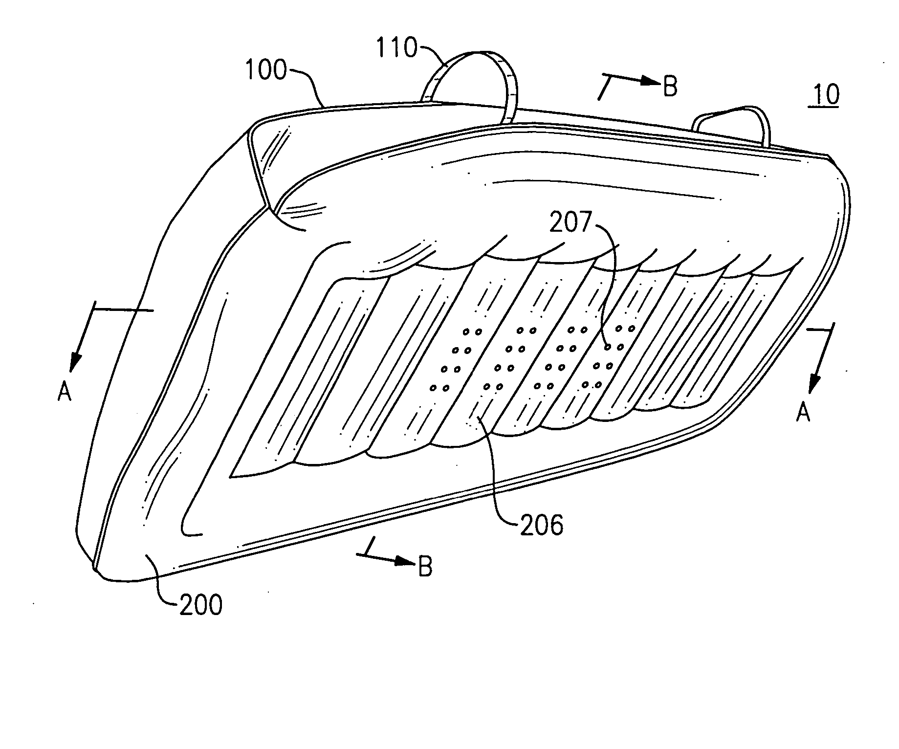
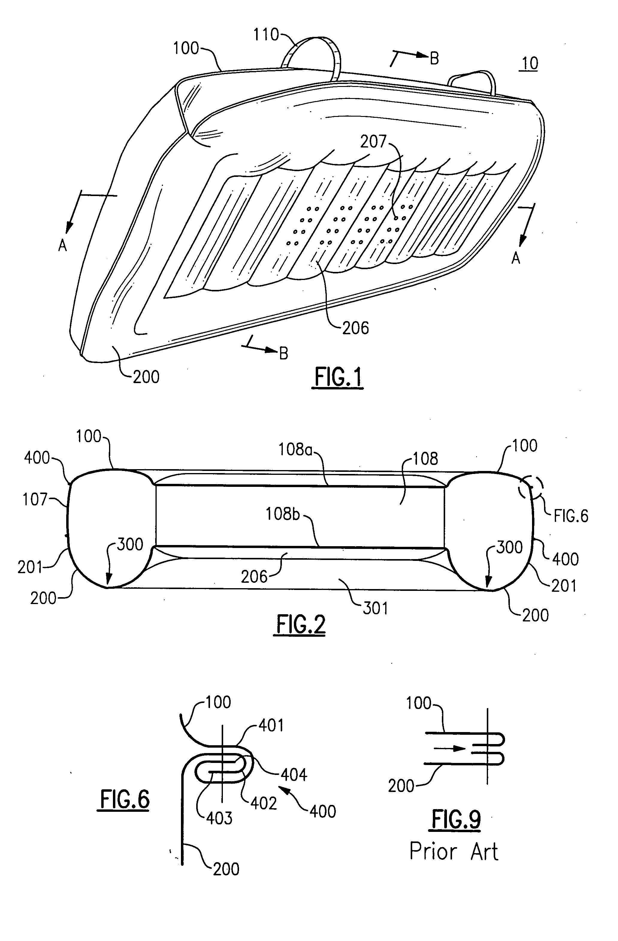
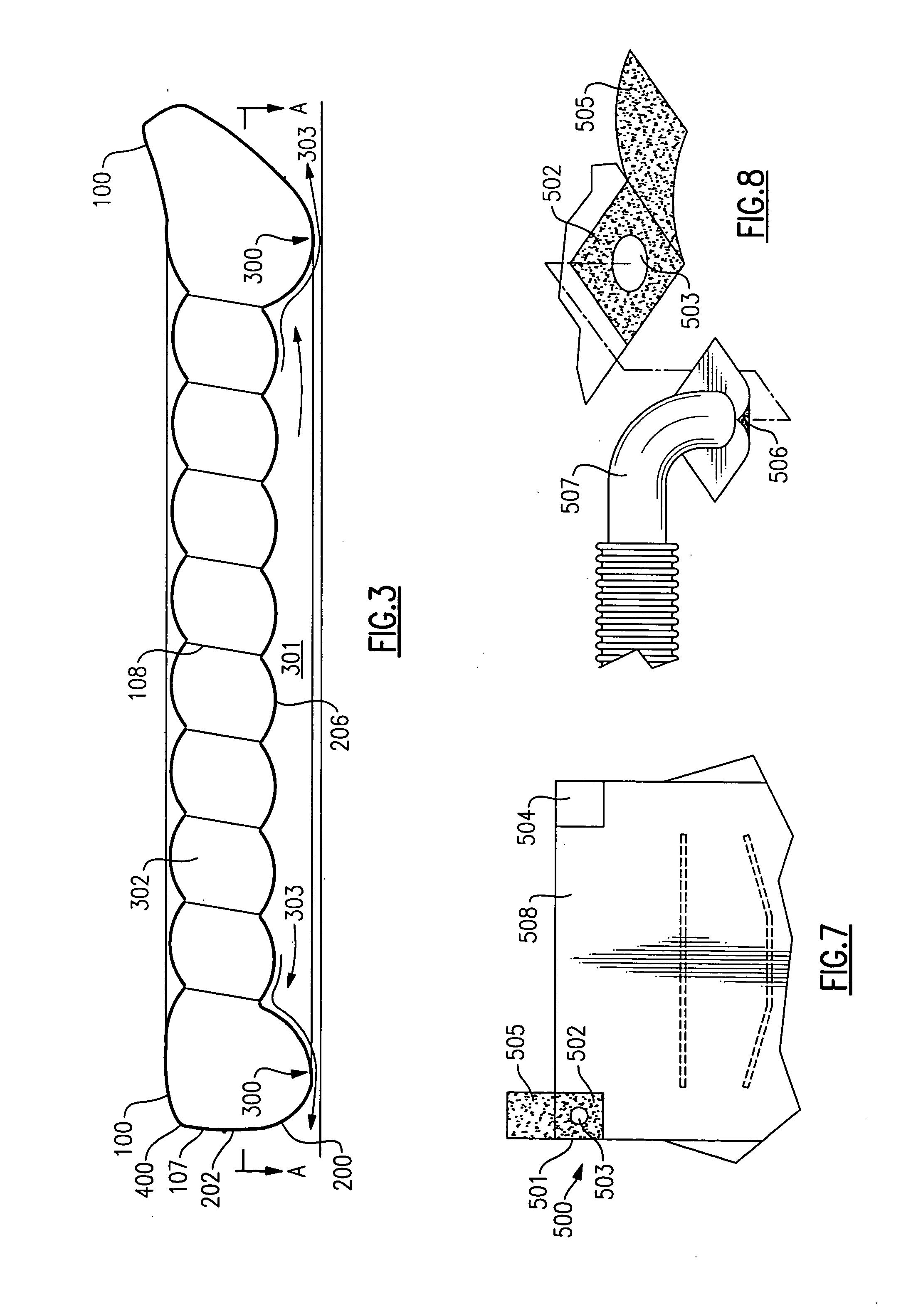
[0043]FIGS. 1-3 show a material mover 10 that includes a plenum chamber 302 (seen more clearly in FIG. 3), from which a fluid, such as air, oil, water or the like, exits through a plurality of orifices 207 to produce a fluid film 303 underneath at least a central portion of material mover 10. The plenum chamber 302 is defined by substantially rectangular top and bottom sheets 100 and 200, respectively, and perimeter side walls 107 connecting portions of the top and bottom sheets to one another.

[0044]FIGS. 4 and 5 show that portions of longitudinal edges 102 of top sheet 100 are connected to perimeter side walls 107, which, in turn, are connected to portions of longitudinal edges 201 of bottom sheet 200. The perimeter side walls 107 extend substantially the entire longitudinal length of lower and middle regions 106 and 105, respectively, of top sheet 100, and lower and middle regions 203 and 204, respectively, of bottom sheet 200. Lateral edges 103 are located in upper region 104 an...


PUM


Abstract

A material mover includes substantially rectangular top and bottom sheets connected to perimeter side walls. The width of the bottom sheet which is perforated with orifices at least in a central portion, is greater than the width of the top sheet at least in middle and lower regions of the top and bottom sheets. A plurality of partition members connect at least portions of the top and bottom sheets to one another, and extend parallel with lateral edges of the top and bottom sheets and are spaced in from the perimeter side walls. A fluid weir is defined at an outer periphery of the bottom sheet to provide a fluid film reservoir under at least the central portion of the bottom sheet having the plurality of orifices formed therein. The dispersion of the fluid from underneath the material mover is inhibited by the fluid weir.

Description

CROSS REFERENCE TO RELATED APPLICATIONS [0001] This application is a continuation of International Application No. PCT / US2003 / 035709, having an international filing date of Nov. 10, 2003, which designated the United States, and which in turn claims the benefit under 35 USC § 19(e) of U.S. Provisional Application Ser. No. 60 / 425,673, filed Nov. 12, 2002, the entireties of which are incorporated herein by reference.FIELD OF THE INVENTION [0002] This invention relates generally to a fluid-elevated material mover, and more particularly to a fluid-elevated material mover providing enhanced control of a fluid film contained underneath the material mover, at least at a central portion thereof, to facilitate easy transfer of a wide variety of objects. BACKGROUND OF THE INVENTION [0003] The need to translocate objects without damaging the object or the transfer surfaces, while conserving electric power and manpower resources, spans the gamut of practical applications. From industrial to medi...

Claims


Application Information

Patent Timeline
Patent Type & Authority Applications(United States)
IPC IPC(8): A47C31/00A61G7/10B60P7/06B60P7/16B60V1/06B65DB65G7/06B66F3/35
CPCA61G7/1021A61G7/1028A61G7/103A61G2200/32B66F3/35B60P7/16B60V1/06B65G7/06B60P7/065
Inventor JOHNSON, RAYNOR A.
Owner GRAY TEK
Why Eureka
Try Eureka