Thermal wall system

a technology of thermal wall and insulation layer, which is applied in the direction of heat-insulating girders, lighting and heating apparatus, etc., can solve the problems of limiting the ability to make on-site modifications, adding to the complexity of manufacturing and fabrication,

Inactive Publication Date: 2005-04-14
NUCONSTEEL
View PDF46 Cites 44 Cited by
  • Summary
  • Abstract
  • Description
  • Claims
  • Application Information

AI Technical Summary

Problems solved by technology

While each of these methods reduces conduction of heat through the areas between framing components, they generally do not address conduction through the components themselves, which may present a direct and continuous path for heat transfer across the wall.
Such construction adds to the complexity of manufacturing and fabrication, and limits the ability to make on-site modifications.

Method used


Image

  • Thermal wall system
  • Thermal wall system
  • Thermal wall system

Examples


Embodiment Construction

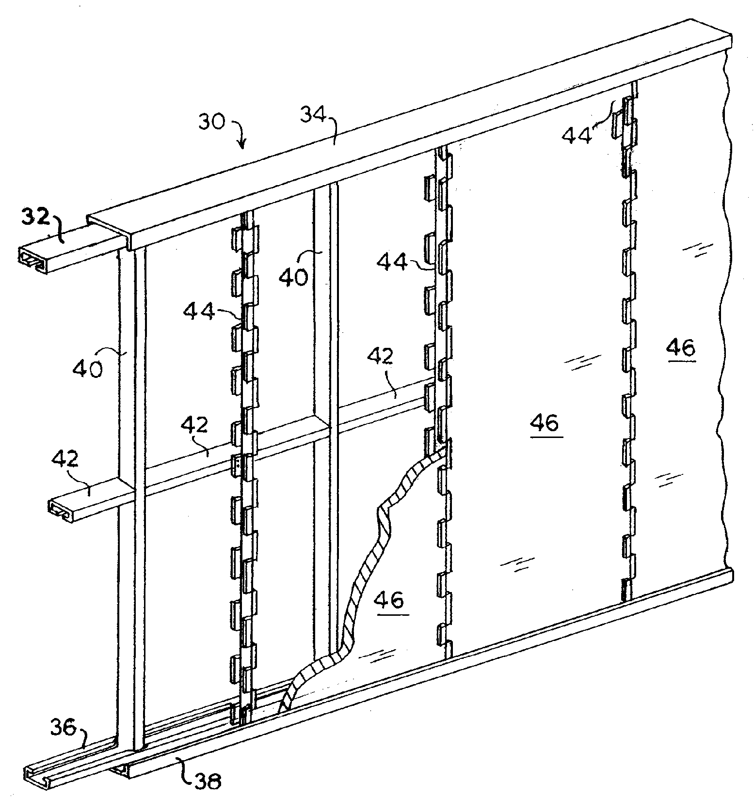
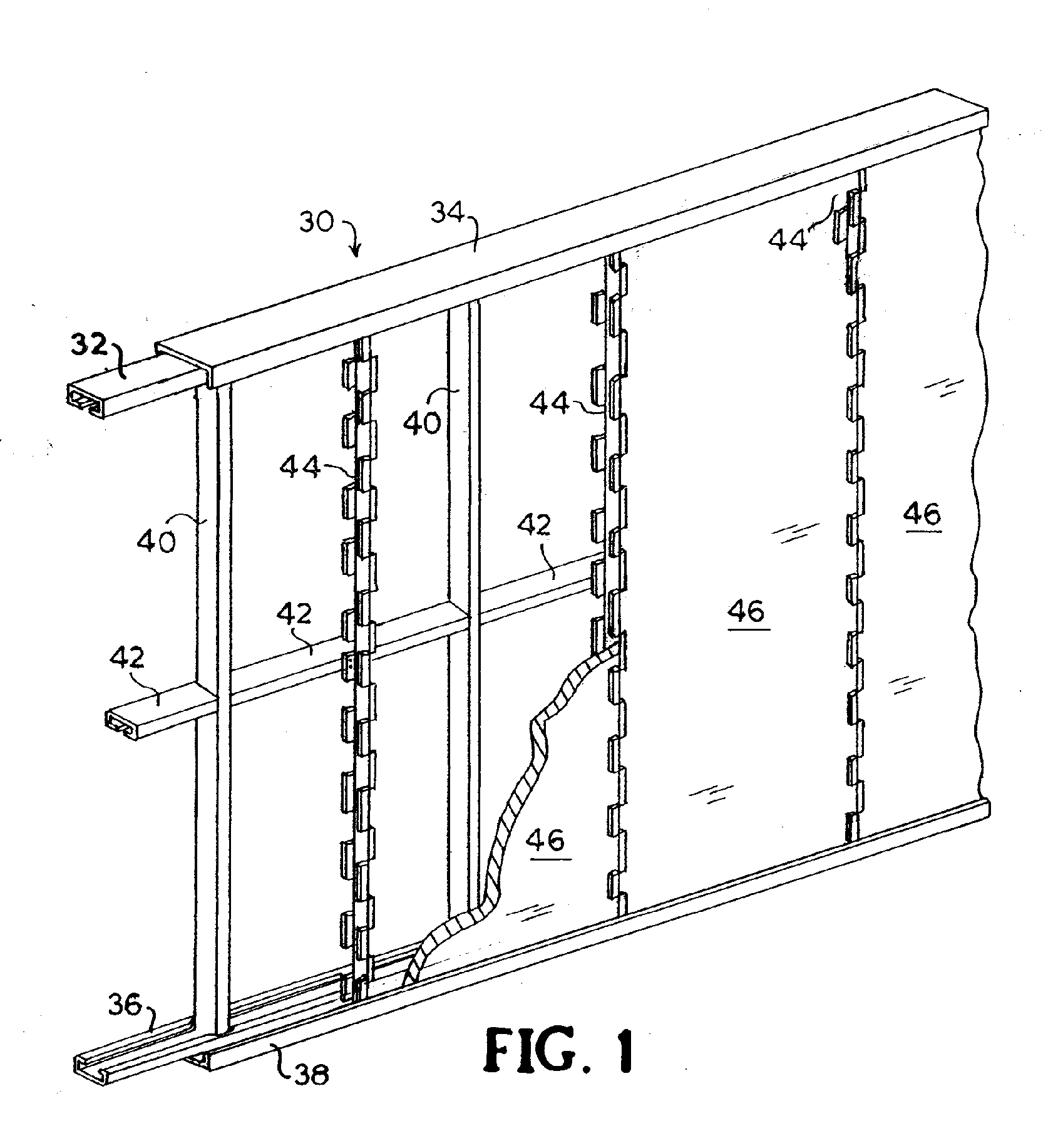
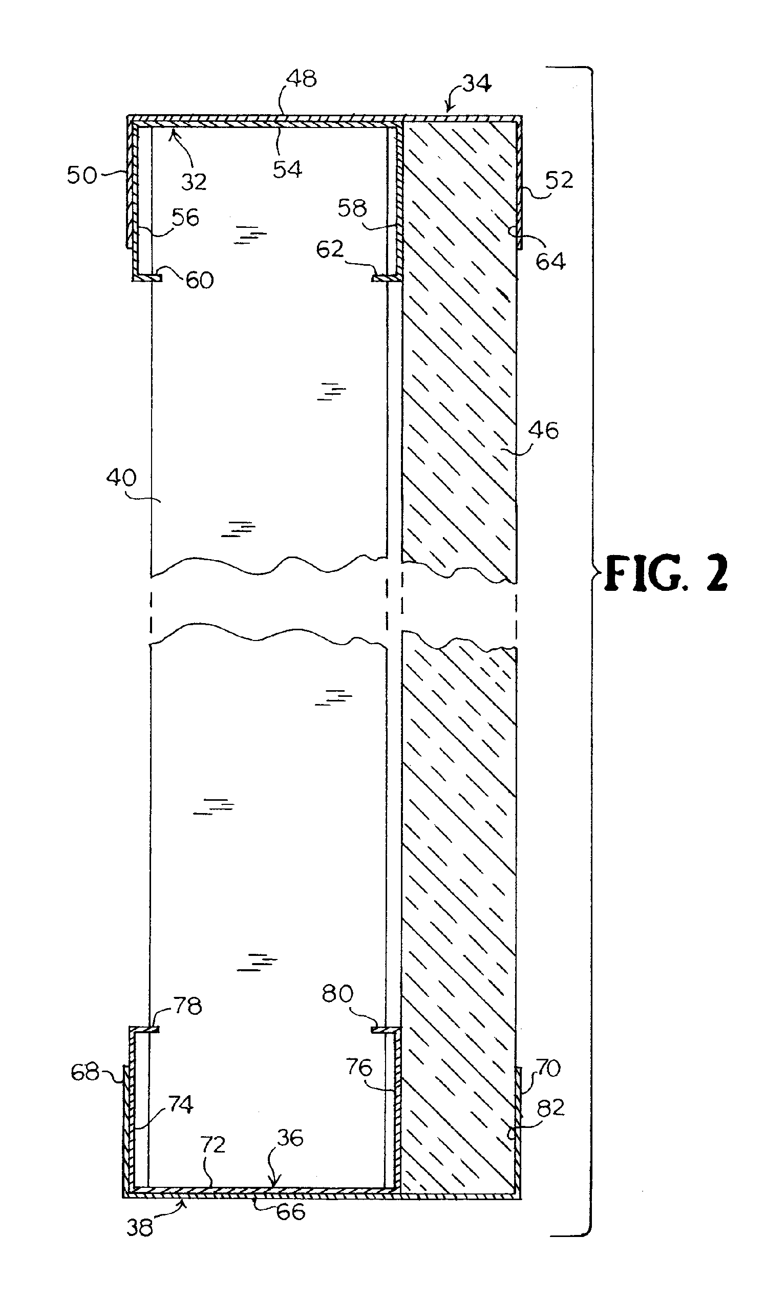
[0024] A thermal wall system of the present invention may receive and secure rigid insulation and may also provide an attachment surface for exterior finish materials. The thermal wall system may reduce conduction of heat through a wall by providing insulation and, as applicable, limiting direct conduction through some structural framing members.

[0025] The thermal wall system may include light gauge steel or other metal, and may be incorporated into conventional and proprietary wall framing components of light gauge steel or wood. The scope of the invention is not intended to be limited by materials or dimensions listed herein, but may be carried out using any materials and dimensions that allow the construction and operation of the present invention. Materials and dimensions depend on the particular application. Metal primary structural framing members may be “C” shaped, “U” shaped, or other shape as selected by one of ordinary skill in the art. Certain relative dimensions, sizes,...


PUM


Abstract

A thermal wall system for slowing heat transfer through walls. The system includes horizontal top and bottom tracks, horizontal top and bottom plates, and vertical studs mounted to and extending between the top and bottom plates. The top tracks and plates have flanges that extend downward. The bottom tracks and plates have flanges that extend upward. The width of the plates fits within the width of the tracks. Top and bottom tracks and plates are respectively nested along their webs and one flange to form a longitudinal opening between their respective opposing flanges. Rigid insulation may be disposed in the longitudinal opening. Thermal framing components may also be provided, extending between the top and bottom plates, to support vertical edges of insulation sheets. Thermal end caps may be used to treat the terminal edges of insulation.

Description

CROSS REFERENCE TO RELATED APPLICATIONS [0001] This application claims priority from co-pending U.S. provisional application 60 / 481,484, filed Oct. 8, 2003, by the inventors hereof, the entire disclosure of which is incorporated herein by reference.BACKGROUND [0002] The present invention relates to thermal insulation of walls, and more particularly to systems for supporting rigid insulation in structural framing applications. [0003] Walls of buildings may include framing made of light gauge steel, wood, or a combination thereof. In addition to structural requirements that the framing must meet, thermal characteristics are important, especially for exterior walls. Minimizing heat transfer through the walls is desirable both for comfort and for energy efficiency of heating and air conditioning. For example, when the outdoors is cold relative to inside a heated structure, heat from indoors should be prevented from passing through the walls to the outdoors. Conversely, when the outdoors...

Claims


Application Information

Patent Timeline
Patent Type & Authority Applications(United States)
IPC IPC(8): E04B1/24E04B1/76E04B2/00E04B2/58E04B2/74F16L59/00F28F13/00
CPCE04B2/58E04B2/7409E04B2001/2481E04B2/7453E04B2/7414
Inventor MOODY, DONALD R.HANSON, COURTNEY J.
Owner NUCONSTEEL
Why Eureka
Try Eureka