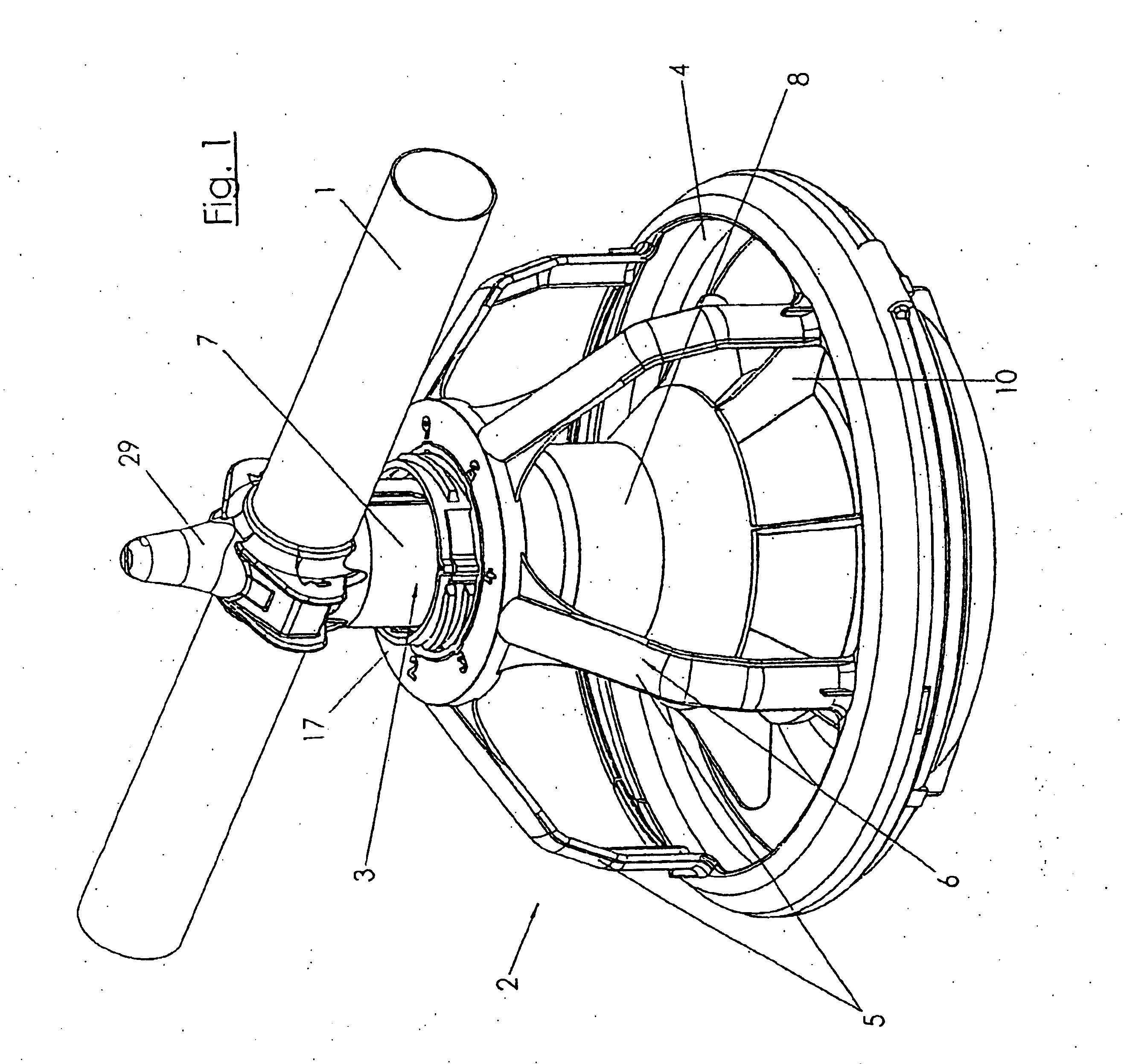
[0047] The device for feeding free-range poultry for fattening kept in a coop, and broilers in particular, consists of at least one feed delivery pipe 1, held above the floor of the coop in a lowerable manner, which runs along the entire length of the coop and, by means of a delivery worm element located inside it, or a cable or a chain with delivery disks, transports feed capable of scatter distribution to individual bowl devices 2 suspended on the feed delivery pipe 1. The parts described can also be designated in their entirety as the feed line.
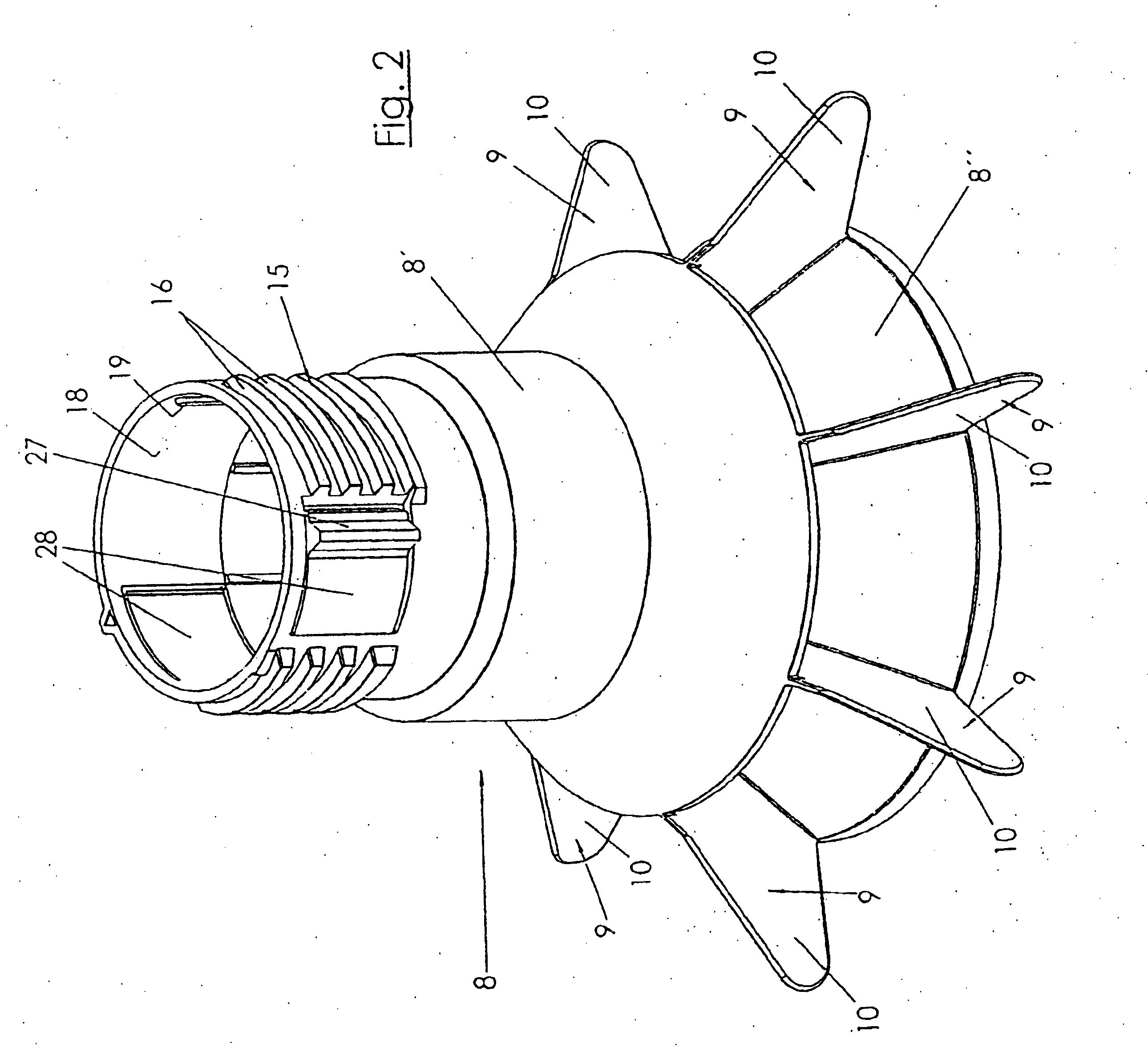
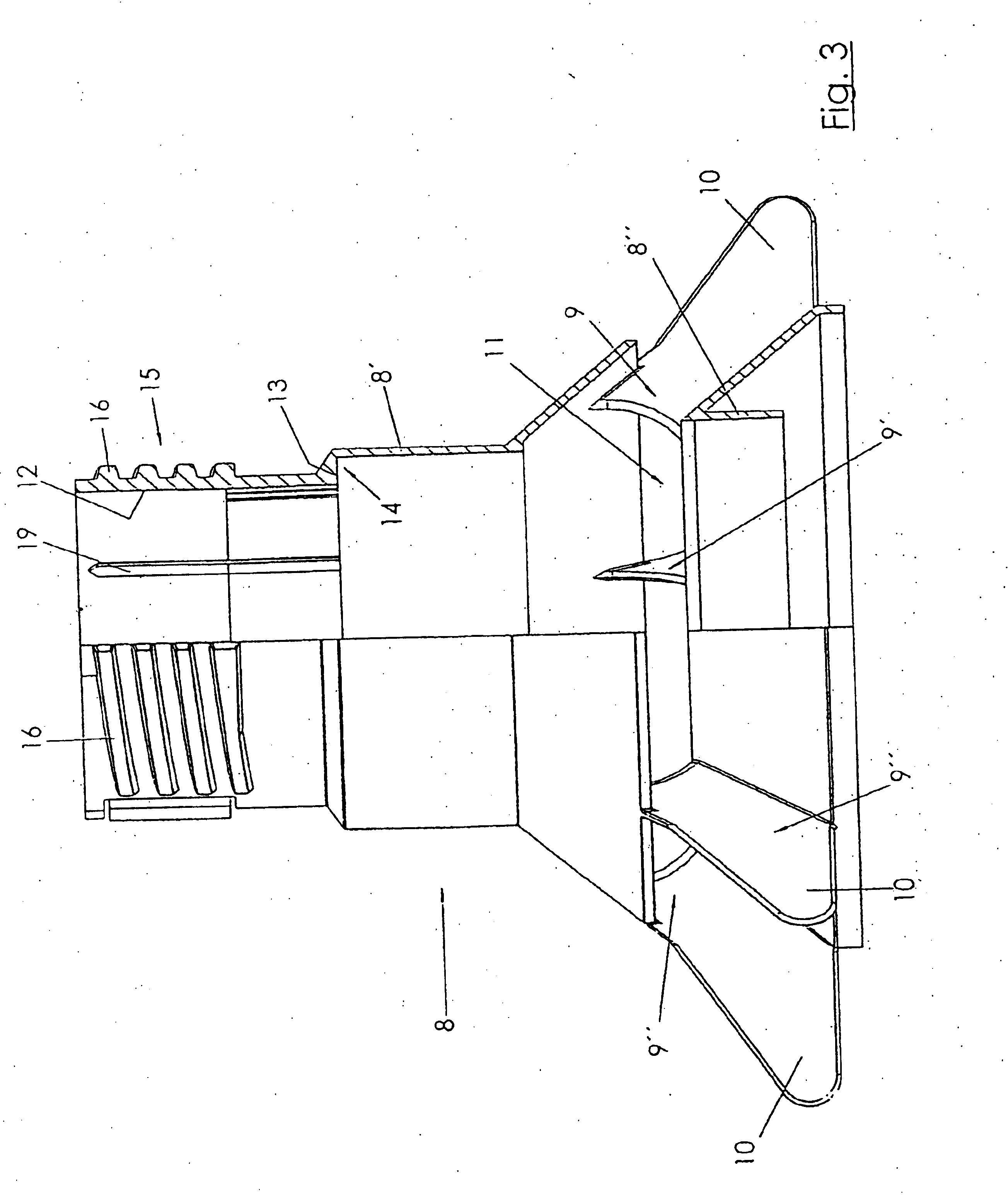
[0048] In FIG. 1, only one part of the feed delivery pipe 1 is represented, with a bowl device 2 suspended in the area of a branch aperture in the feed delivery pipe 1. The bowl device 2 comprises a downpipe 3, departing from a branch aperture not further visible here, and a feed bowl 4 located beneath the downpipe 3, with bowl cupolas 6 formed from grid bars 5 running in spoke fashion. In this situation, the downpipe 3 consists of an inner cylinder 7, departing from the branch aperture not visible here, and an outer cylinder 8, surrounding the inner cylinder 7, on which the bowl 4 is suspended by means of the grid bars 5 of its bowl cupola 6, in such a way that, when the feed delivery pipe 1 is lowered, it comes to rest, and in particular comes to rest on the floor 34 of the coop, not represented any further here. The outer cylinder 8 is guided in rotatable fashion at the inner cylinder 7 and in a raisable and lowerable manner, whereby at least one lifting stop is provided to delimit the lifting and lowering path, which will be described in greater detail hereinafter.
[0049]FIG. 2 shows a view of the outer cylinder 8.
[0050] In FIG. 3, a side view of the outer cylinder 8 according to FIG. 2 is shown, in a half-section.
[0051]FIGS. 2 and 3 are explained in greater detail hereinafter.
[0052] The outer cylinder 8 consists of adjacent cylinder sections 8′ and 8″, co-axial to each other. The cylinder sections 8′ and 8″ are connected to each other by means of bridging elements 9, each of which is designed as a paddle or vane 10, projecting over the periphery of the outer cylinder 8 into the feed bowl 4. The bridging elements 9 bridge the gap area 11, which corresponds to the distance between the cylinder sections 8′ and 8″ of the outer cylinder 8, or in this case its upper cylinder section 8′, features a recess 13, which is part of a lifting stop 14. The outer surface of the upper cylinder section 8′ of the outer cylinder 8 is designed in the upper end part as a threaded spindle 15, which has screw threads 16.
[0053] The outer cylinder is made of suitable plastic material, with the result that the screw threads 16 and therefore the threaded spindle 15 can be shaped without problem during the manufacture of the outer cylinder 8.
[0054] As FIG. 1 also shows, the free ends of the grid bars 5 of the bowl cupola 6 are connected to a screw ring 17, which can be screwed onto the area designed as a threaded spindle 15 of the cylinder section 8′ of the outer cylinder 8.
[0055] At the rotation of the feed bowl 4, relative to the outer cylinder 8, the threaded spindle 15 causes a movement of the feed bowl 4 in respect of the height, towards the lower end of the cylinder section 8″ with the vanes 10 of the outer cylinder 8.
[0056]FIGS. 2 and 3 further show that a rotational stop delimiting the rotational path of outer cylinder 8 in relation to the inner cylinder 7 features a driver dog 19, located in this case on the inner surface 18 of the outer cylinder 8, into the rotation path of which he elevation 21 arranged on the outer surface 20 of the inner cylinder 7 projects during the rotation of the outer cylinder 8 about the inner cylinder 7.
[0057]FIG. 4 shows a view of the inner cylinder 7, which consists of cylinder sections 7′ and 7″, whereby the open gap area between the cylinder sections 7′ and 7″ is again bridged by bridging elements 23 in flat web form. In FIG. 4, a part of the lifting stop 14 is visible, which at the inner cylinder 7 is designed as at least one abutment shoulder 24 for the recess 13 in the outer cylinder 8, projecting radially from the inner cylinder 7.
[0058]FIG. 4 shows that each abutment shoulder 24 for the recess 13 is a part of a radial projection 25 of the inner cylinder 7, similar to a collar flange in shape. FIG. 4 also shows that the outer surface 20 of the inner cylinder 7, in the upper area and therefore in the area of its head part, is offset by means of a reduced cylinder diameter in relation to the other part of the cylinder section 7′ of the inner cylinder 7. The offsetting step is designated by 26.
[0059]FIG. 2 further shows that, to provide securing against rotation of the structural unit consisting of the screw ring 17 (FIG. 1) with bowl cupola 6 and the feed bowl 4, there is provided at each outer cylinder 8, in its area designed as a threaded spindle 15, two spring-elastic engagement cams 27. Each engagement cam 27 is connected by means of a spring-elastic tongue 28 to the outer cylinder 8. In this situation, removal from the mold is effected in such a way that the tongues are wall parts of the outer cylinder, formed by insertion cuts, which are capable of springing from the outside inwards under radial pressure and can be moved back elastically into the initial position when the pressure is released. In the pressureless initial position, the tongues 28 are flush again with the wall of the outer cylinder 8.
[0060]FIG. 5 shows a side view of the inner cylinder, whereby the right half of the inner cylinder is shown in a longitudinal section.
[0061] The same components are designated with the same reference numbers.
[0062]FIG. 4 in particular shows that the inner cylinder 7 in its upper free end is involved in the formation of a pipe adapter, in that a bowl half 29 of the pipe adapter is formed on the inner cylinder 7. This bowl half can be supplemented to form the pipe adapter by the imposition of an upper part 30, which is visible in FIG. 1, which encompasses the feed pipe 1 in the area of a branch aperture, not further shown, in such a way that the branch aperture is flush with the fall aperture 31 in the upper bowl part 29 of the inner cylinder 7. Feed emerging from the feed delivery pipe passes over the branch aperture and the fall aperture 31 into the inner cylinder, and can fall into the feed bowl via the gap area 22 or into the lower fall aperture 32. The lower fall aperture 32 is circumscribed by the lower edges 33 of the cylinder section 7″.
[0063]FIG. 6 shows, in a side view, a bowl device 2 suspended on a feed delivery pipe 1, whereby the right-hand side is shown in section. The same components are designated with the same reference numbers.
[0064] It can be seen from FIG. 6 that the inner cylinder 7 is designed in such a way that its end-side cylinder section 7″ covers the gap area 11 between the cylinder sections 8 and 8″ of the outer cylinder 8, when the outer cylinder 8 is moved by a raising of the feed delivery pipe 1 into a position which is lowered in relation to the inner cylinder 7, in which the parts forming the lifting stop 14 are in opposing positions. With this embodiment, it can be seen in FIG. 6 that the outer cylinder 8, with the step surface formed by its recess 13 in the cylinder section 8′, is in contact on the abutment shoulder 24 of the radial projection 25 of the inner cylinder 7. Feed material entering the inner cylinder 7 from the feed delivery pipe is represented here by dots, and trickles into the feed bowl 4, whereby it trickles out of the lower fall aperture 32 of the inner cylinder 7 into the cylinder section 8″ of the outer cylinder 8, and from there directly into the feed bowl 4. This feed covers the conically-shaped floor of the feed bowl 4, likewise made of plastic, in a flat dispersal, as can be seen here. Poultry running about on the floor 34 of the coop can reach the feed located in the depth of the feed bowl 4.
[0065] The height of the dispersal cone of feed above the floor of the feed bowl 4 is adjustable. To regulate the feed level, or to adjust what is referred to as the feed stand position, the screw ring 17, to which the grid bars 5 of the bowl cupola 6 are connected, is rotated about a height axis. Depending on the rotation path and pitch of the screw threads 16, the position of the bowl is displaced in relation to the lower emergence edge 35 of the lower free end of the outer cylinder section 8″.
[0066]FIG. 7 is a sectional view along the line VII-VII in FIG. 6. The same components are designated by the same reference numbers. FIG. 7 shows that the inner cylinder 7, of which the cylinder section 7′ is visible here, is encompassed by the outer cylinder 8, or by its cylinder section 8′, visible here. The outer cylinder, in the position represented here, is therefore freely rotatable about the inner cylinder 7. In FIG. 7, the driver dogs 19 can be seen which are arranged on the inner surface of the outer cylinder 8.
[0067] The screw ring 17 features on its inner circumferential surface 36 cut-outs 37. Engagement cams 27, which are mounted on the spring-elastic tongues 28, can engage with the cut-outs 37, so that the screw ring 17, with the engagement cams 27 engaged in the cut-outs 37, cannot be rotated in relation to the outer cylinder 8. The feed level, once set, can be maintained. In the event of rotational forces being imposed on the feed bowl or via its bowl cupola on the screw ring 17, the unit consisting of the outer cylinder 8, screw ring 17, bowl cupola 6 and feed bowl 4 will rotate only in relation to the inner cylinder 7. The inner cylinder 7 cannot rotate together because of its suspension on the feed delivery pipe 1.
[0068]FIG. 8 shows a side view according to FIG. 6, whereby the right half is in turn shown in section. The feed delivery pipe is lowered in the position shown in FIG. 8, so that it runs at a slight distance above the floor 34 of the coop. The feed bowl 4, in the position shown in FIG. 8, rests on the floor 34 of the coop, as a result of which the unit formed by the outer cylinder with the bowl cupola 6 and the feed bowl 4 is raised in relation to the inner cylinder 7. In this position, the recess 13 forming the lifting stop 14 and the abutment shoulder 24 of the inner cylinder 7 are no longer in mutually opposed positions. The outer cylinder 8 with its cylinder sections 8′ and 8″ are therefore raised in relation to the inner cylinder to such an extent that the gap area 11 between the cylinder sections 8′ and 8″ of the outer cylinder 8 is congruent with the gap area 22 between the cylinder sections 7′ and 7″ of the inner cylinder 7. As a result of the congruent open gap areas 11 and 22, which form a “360° window”, the feed can additionally pass to the lower fall aperture 32 into the feed bowl 4, as is represented here by dots. The feed level in the feed bowl 4 is simultaneously higher, with the result that even young animals, such as chicks, can reach over the edge of the feed bowl 4 to the feed, which now stands higher in the feed bowl 4.
[0069]FIG. 8 also indicates that the upper area of the cylinder section 8′ of the outer cylinder 8, which is provided with screw threads 16, onto which the threaded ring 17 is screwed, are now raised to such an extent that the driver dogs 19, not visible here, can be brought into effective connection by means of an elevation 21 or 21′ of the inner cylinder 7.
[0070]FIG. 9 again shows that the elevations 21 and 21′ on the outer surface 20 of the cylinder section 7′ of the inner cylinder 7 can come in contact with the driver dogs 19, which project from the inner surface 18 of the cylinder section 8′ of the outer cylinder 8. The driver dogs 19 of the fixed inner cylinder 7 prevent the further rotation of the outer cylinder 8 beyond the position of the elevation 21 and 21′. The outer cylinder 8 can therefore only be rotated through 180° in each case, and further rotation is accordingly stopped by the elevation 21 or 21′ respectively. If the outer cylinder is nevertheless rotated further, for example in order to change the level of the feed with the aid of the threads on the outer cylinder and with the aid of the screw ring 17, then the engagement cams 27, because of their oblique flanks 38, will be pressed out of the cut-outs 37 in the screw ring, said cut-outs also being provided with oblique edges 39. The engagement cams 27 are in this situation deflected inwards, and specifically against the elastic resetting force of the tongues 28. With the corresponding further rotation into the next feed position, which is indicated here by numbers on the screw ring, the engagement cams 27 can engage again in the next cut-out 37, as shown in FIG. 7.
[0071]FIG. 10 shows the view of a bowl device, of which the bowl cupola has been left out for simplification of the internal arrangements of the feed bowl 4. The same components are designated with the same reference numbers.
[0072]FIG. 10 shows in particular that the feed bowl 4 features a feed plate, which in the area of its plate edge 40 features connecting elements 41 and 42 for connection to the bowl cupola 6, not visible here. The connecting elements 41 and 42 comprise a folding joint 43 and at least one locking or retention element 44. A ring surface of the feed plate, which runs around the plate center located beneath the downpipe 3, is subdivided into feeding sections, whereby each feeding section consists of at least one pocket, one field, or similar shaped area 45, delimited by depression or elevation. The number of feeding sections is equal to a multiple of the number of the bridging elements 9 of the outer cylinder 8, formed as paddles or vanes 10, of which the cylinder sections 8′ and 8″ are visible here, with the gap area 11 located between them.
[0073] The above description is considered that of the preferred embodiment only. Modification of the invention will occur to those skilled in the art and to those who make or use the invention. Therefore, it is understood that the embodiment shown in the drawings and described above is merely for illustrative purposes and not intended to limit the scope of the invention, which is defined by the following claims as interpreted according to the principles of patent law, including the doctrine of equivalents.