

Apparatus for dispensing fluid
- Summary
- Abstract
- Description
- Claims
- Application Information
AI Technical Summary
Benefits of technology
Problems solved by technology
Method used
Image

Examples
Embodiment Construction
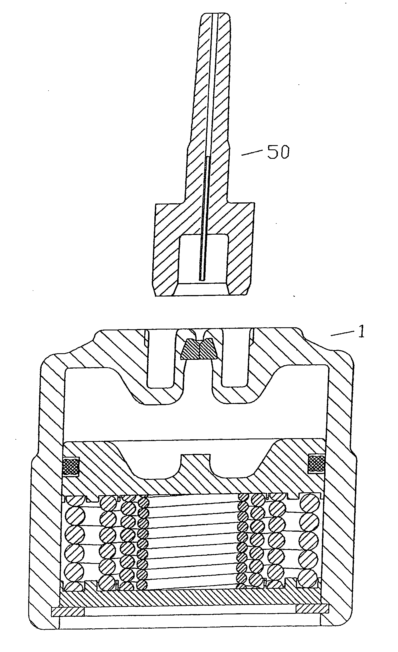
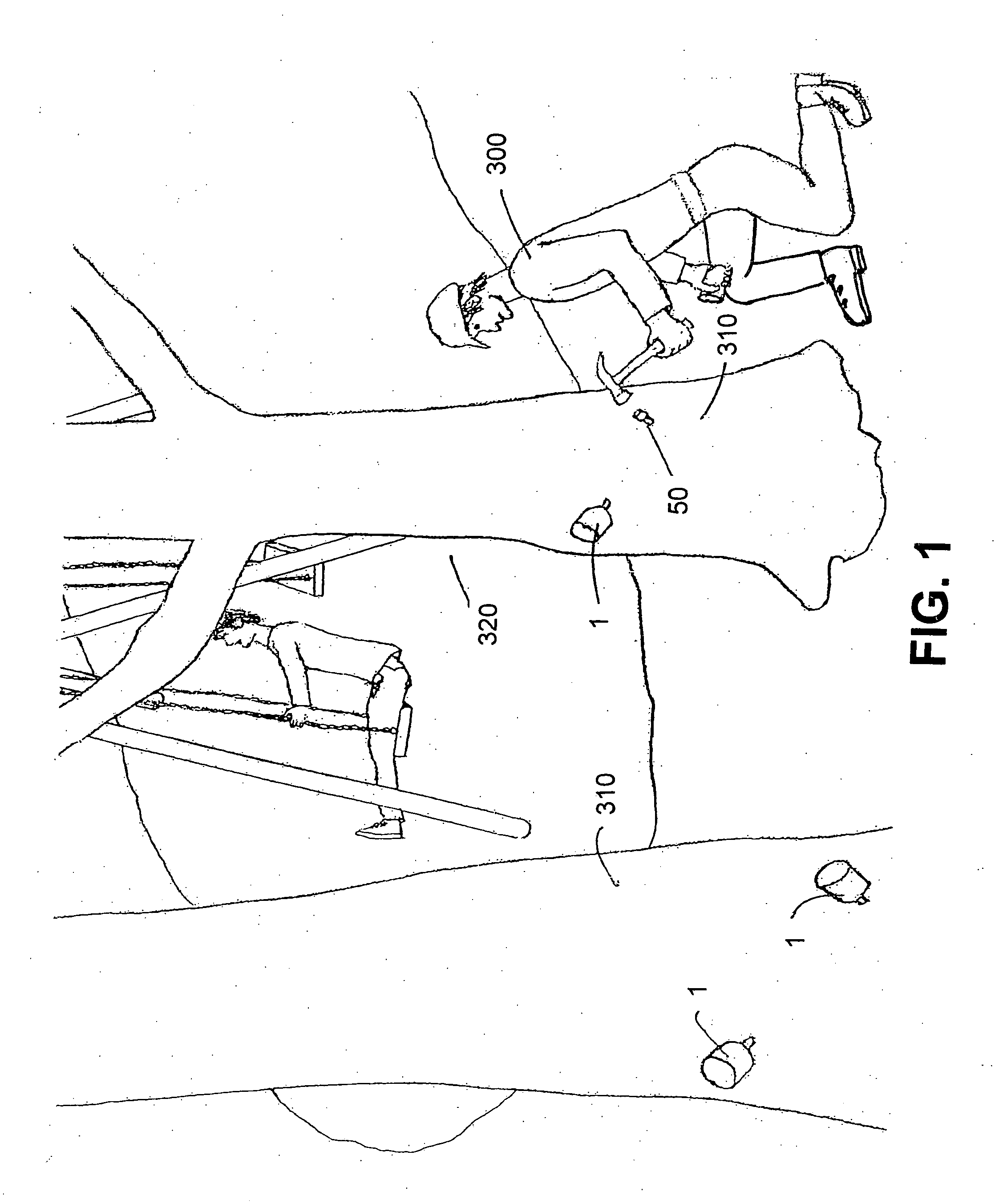
[0044] In FIG. 1, a worker 300 is in the process of installing a series of canisters 1 and injection nozzles 50 into a number of trees 320. This is done by drilling holes in the trees 320, inserting an injection nozzle 50 into each hole and mating a canister 1 to each of the injection nozzles 50.
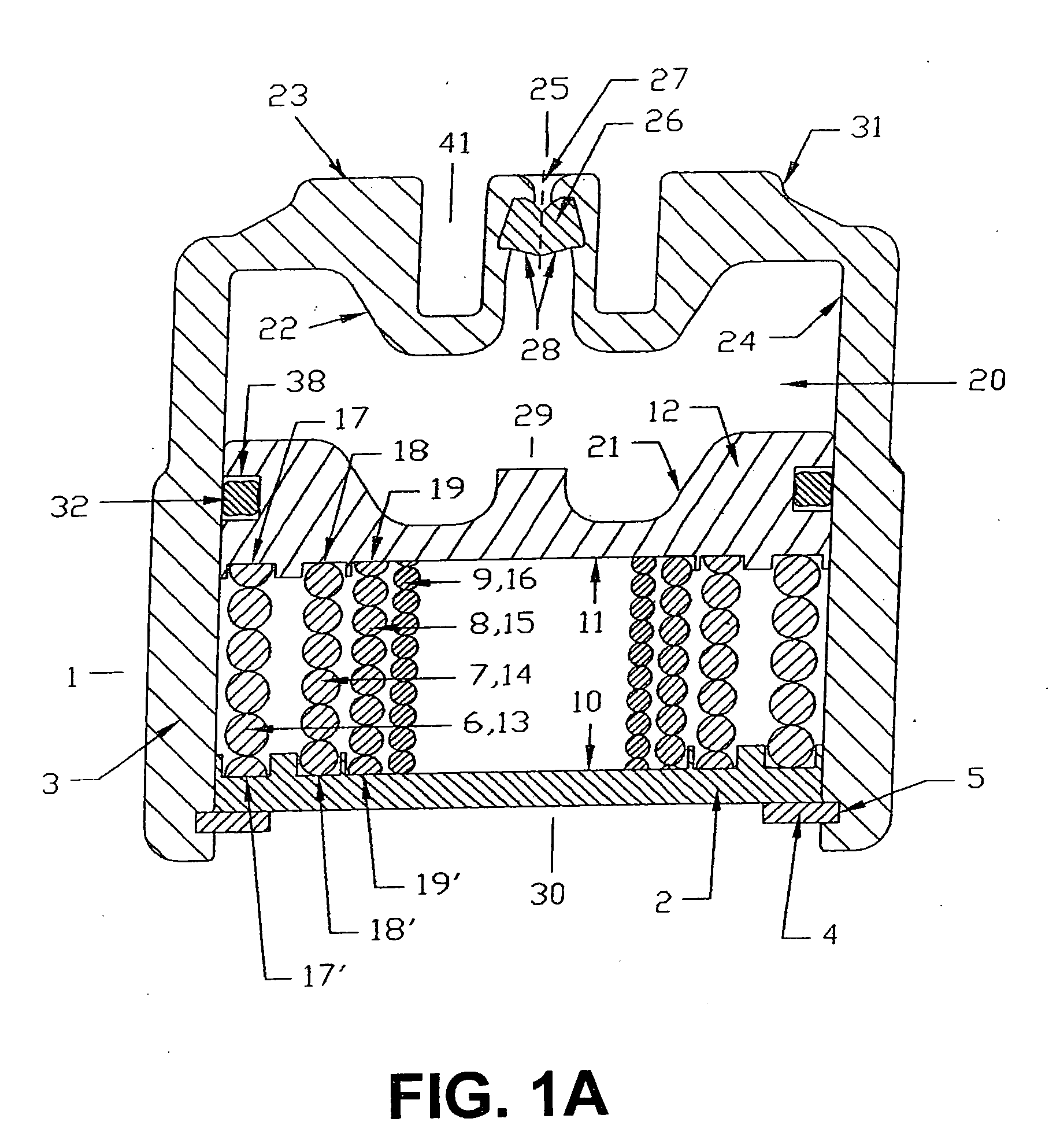
[0045]FIG. 1A depicts a vertical cross-section of the canister 1 of the fluid dispensing apparatus of the present invention. Here, we can see the base 2 disposed at the bottom end of cylinder 3. The base 2 is retained within cylinder 3 by a retaining ring 4 disposed in a groove 5 situated near the bottom end of cylinder 3. Compressed, nested coil springs 6, 7, 8 and 9 of differing gauges are shown disposed between the top surface 10 of the base 2 and the bottom surface 11 of the moveable partition 12. The springs 6, 7, 8 and 9 are generally made of wire and are depicted here as having wire cross-sections 13, 14, 15, and 16 that decrease with the spring label number and a number of turns per...
PUM
 Abstract
Description
Claims
Application Information