
Cooling aft end of a combustion liner

Inactive Publication Date: 2006-01-19
GENERAL ELECTRIC CO
View PDF6 Cites 7 Cited by
  • Summary
  • Abstract
  • Description
  • Claims
  • Application Information

AI Technical Summary

Benefits of technology

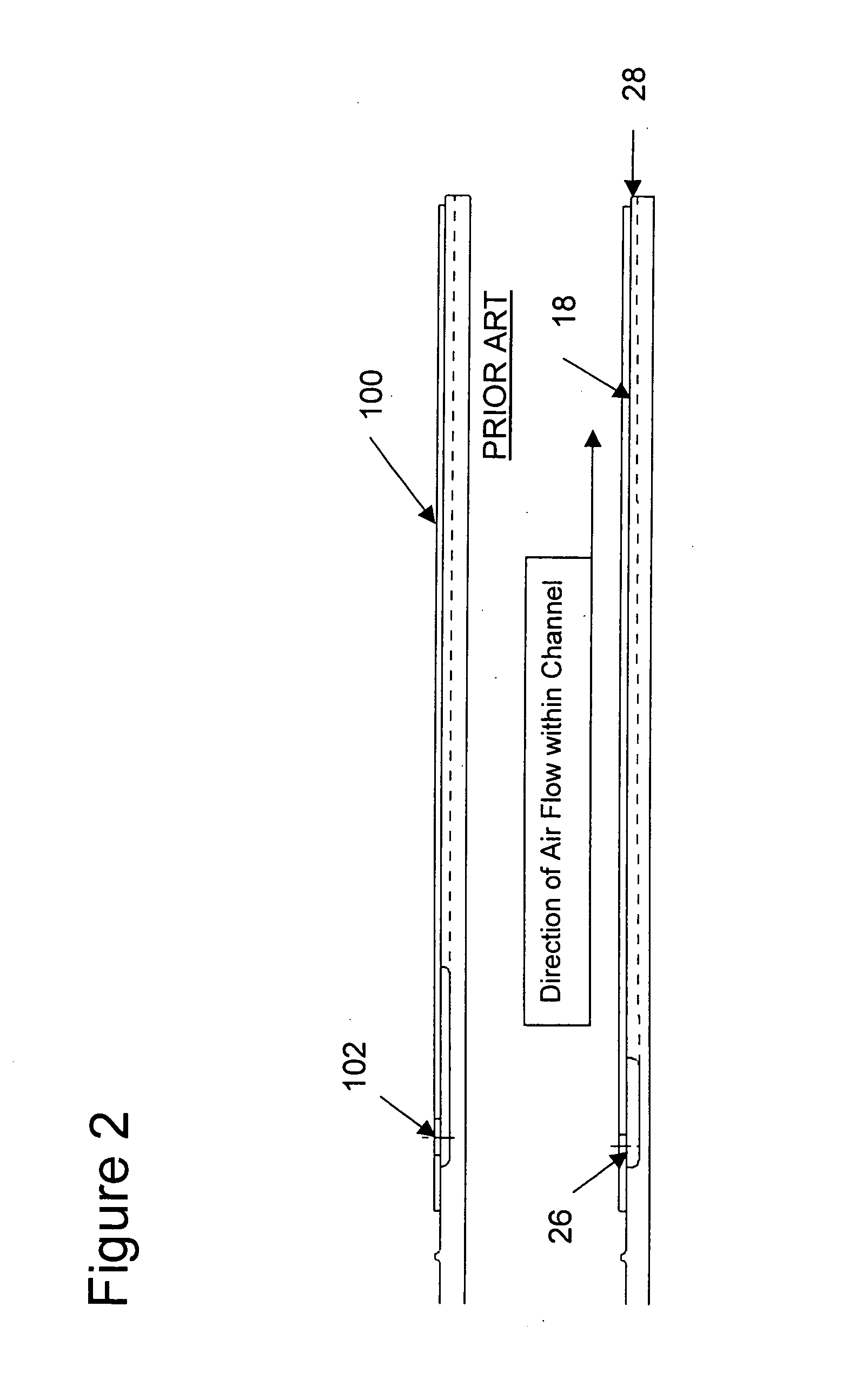
[0006] Briefly stated, the present invention is directed to an improved liner construction for enhancing the cooling in the transition region of a turbine engine between its combustion and discharge sections. The improvement of the invention comprises a liner having an air flow or cooling passage whose cross-section varies along the length of the liner. That is, the height of the channel decreases along the length of the liner from an air inlet to an air outlet of the liner. In one embodiment of the invention, the height of the liner is reduced by approximately 60% from the inlet to the outlet end of the liner. Decreasing the height of the air flow channel in this way increases the cooling effect of air flowing through the channel, results in more more uniform metal temperatures, and reduces thermal stresses, partricularlt at the aft, air outlet end of the liner.
[0007] Optimizing the backside cooling of the aft end of the liner has significant advantages over current liner constructions. A particular advantage is that because of the improvement in cooling with the new liner, less air is required to flow through the liner; and, there is a balancing of the local velocity of air in the liner passage with the local temperature of the air. This now provides a constant cooling heat flux along the length of the liner passage. As a result of this, there are reduced thermal gradients and stresses within the liner. The reduced cooling air requirements also help prolong the service life of the liner. Finally, the reduced air flow requirements allows more air to be directed to the combustion section of the turbine to improve combustion and reduce turbine emissions.

Problems solved by technology

A problem with this that the resultant cooling has been found to be not uniform; but rather there is a substantial temperature gradient between one section of the liner and another.
This results in a degraded effectiveness of the cooling.

Method used


Image

  • Cooling aft end of a combustion liner
  • Cooling aft end of a combustion liner
  • Cooling aft end of a combustion liner

Examples


Embodiment Construction

[0016] The following detailed description illustrates the invention by way of example and not by way of limitation. The description clearly enables one skilled in the art to make and use the invention, describes several embodiments, adaptations, variations, alternatives, and uses of the invention, including what is presently believed to be the best mode of carrying out the invention.

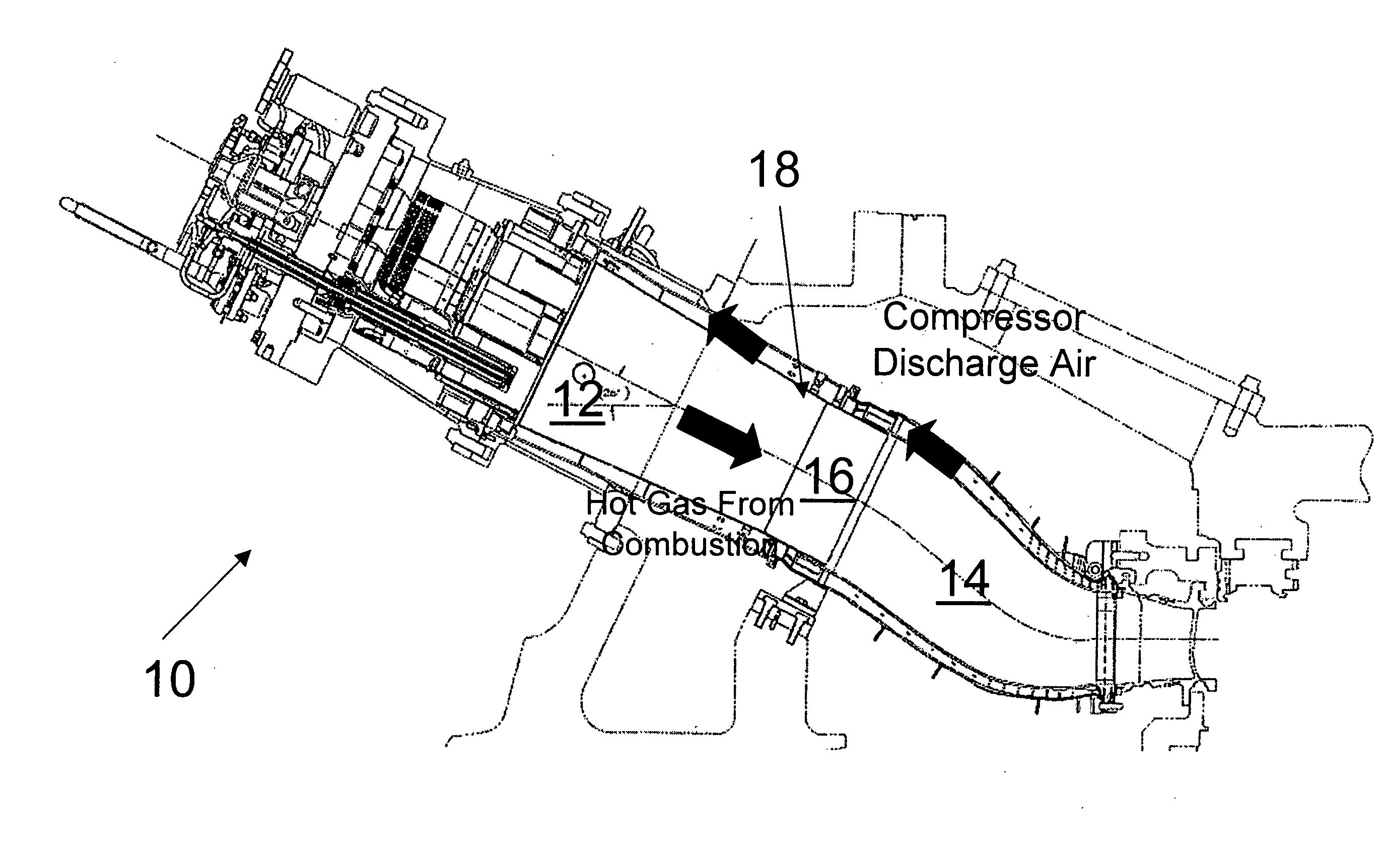
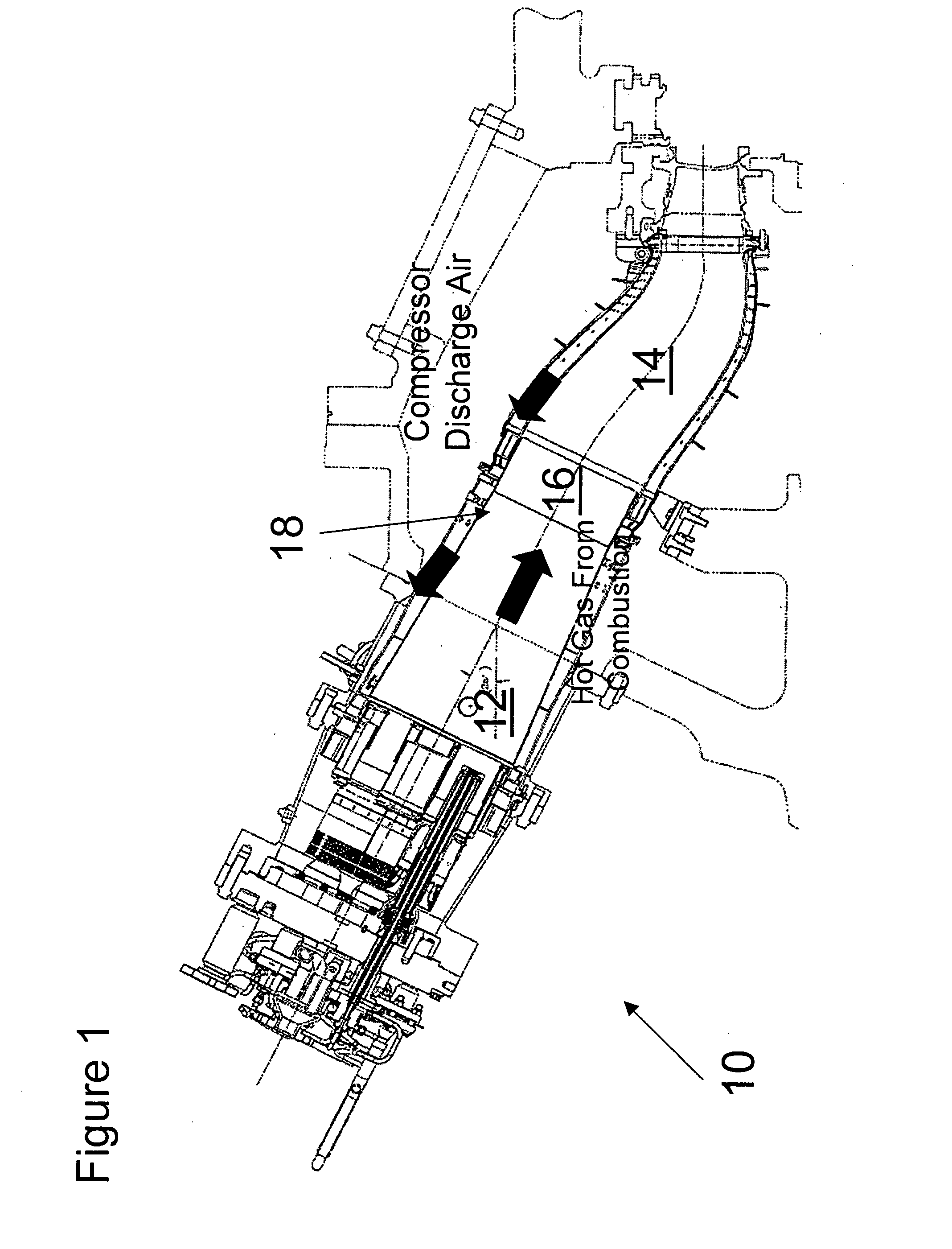
[0017] Referring to the drawings, a turbine engine is indicated generally 10 in FIG. 1. Engine 10 has a combustion section 12 where air drawn into the engine is combusted with a fuel. The engine further includes a discharge section 14. Hot gases from the combustion in section 12 flow from section 12 into section 14. There is a transition region indicated generally 16 between these two sections. As previously noted, the temperature at the aft end of section 12, the inlet portion of region 16, is on the order of 2800°-3000° F. However, the temperature at the downstream, outlet portion of region 16 is pref...


PUM


Abstract

A liner (18) installed in a transition region (16) between a combustion section (12) of a gas turbine engine (10) and an air discharge section (14) of the turbine. The liner has an air inlet (26) for admitting air into the liner, and an air outlet (28) by which air is discharged from the liner. Flow of air through the liner acts to cool air flowing through the transition region of the turbine between the combustion and air discharge sections thereof, so to lower the temperature from between 2800-3000° F. to around 1400-1550° F. The liner has at least one channel (C1, C2) formed in it for flow of air through the liner. The height of this channel uniformly decreases along the length of the channel from the liner's air inlet to its air outlet. This liner construction reduces the thermal strain occurring at the aft end of the liner, prolonging the useful life of the liner, while reducing the amount of air needed to flow through the liner to affect a desired level of cooling in the transition region.

Description

CROSS-REFERENCE TO RELATED APPLICATIONS [0001] None. STATEMENT REGARDING FEDERALLY SPONSORED RESEARCH OR DEVELOPMENT [0002] Not Applicable. BACKGROUND OF THE INVENTION [0003] This invention relates to internal cooling within a gas turbine engine; and more particularly, to apparatus providing better and more uniform cooling in a transition region between a combustion section and discharge section of the turbine. The apparatus, which comprises a liner of an improved design, minimizes thermal stresses in the region, while increasing the effectiveness of cooling in the region, reduces the amount of cooling air required in this portion of the turbine. This allows more air to be directed the combustion section of the turbine which improves combustion of fuel and reduces emissions (NOx). [0004] A gas turbine engine has an air inlet section, a fuel combustion section, and an aft discharge section. There is a transition region between the combustion section of the turbine and the discharge s...

Claims


Application Information

Patent Timeline
IPC IPC(8): F02C7/12
CPCF23R3/002F23R2900/03043F23R2900/03042F23R3/04
Inventor INTILE, JOHN C.FARRELL, THOMAS R.
Owner GENERAL ELECTRIC CO
Learn More