Turbine component including mixed cooling nub feature

Active Publication Date: 2017-05-25
RAYTHEON TECH CORP
View PDF10 Cites 0 Cited by
  • Summary
  • Abstract
  • Description
  • Claims
  • Application Information

AI Technical Summary

Benefits of technology

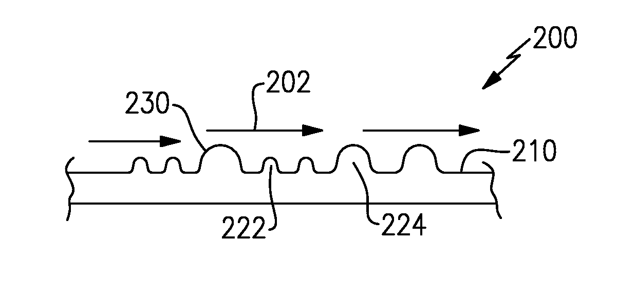
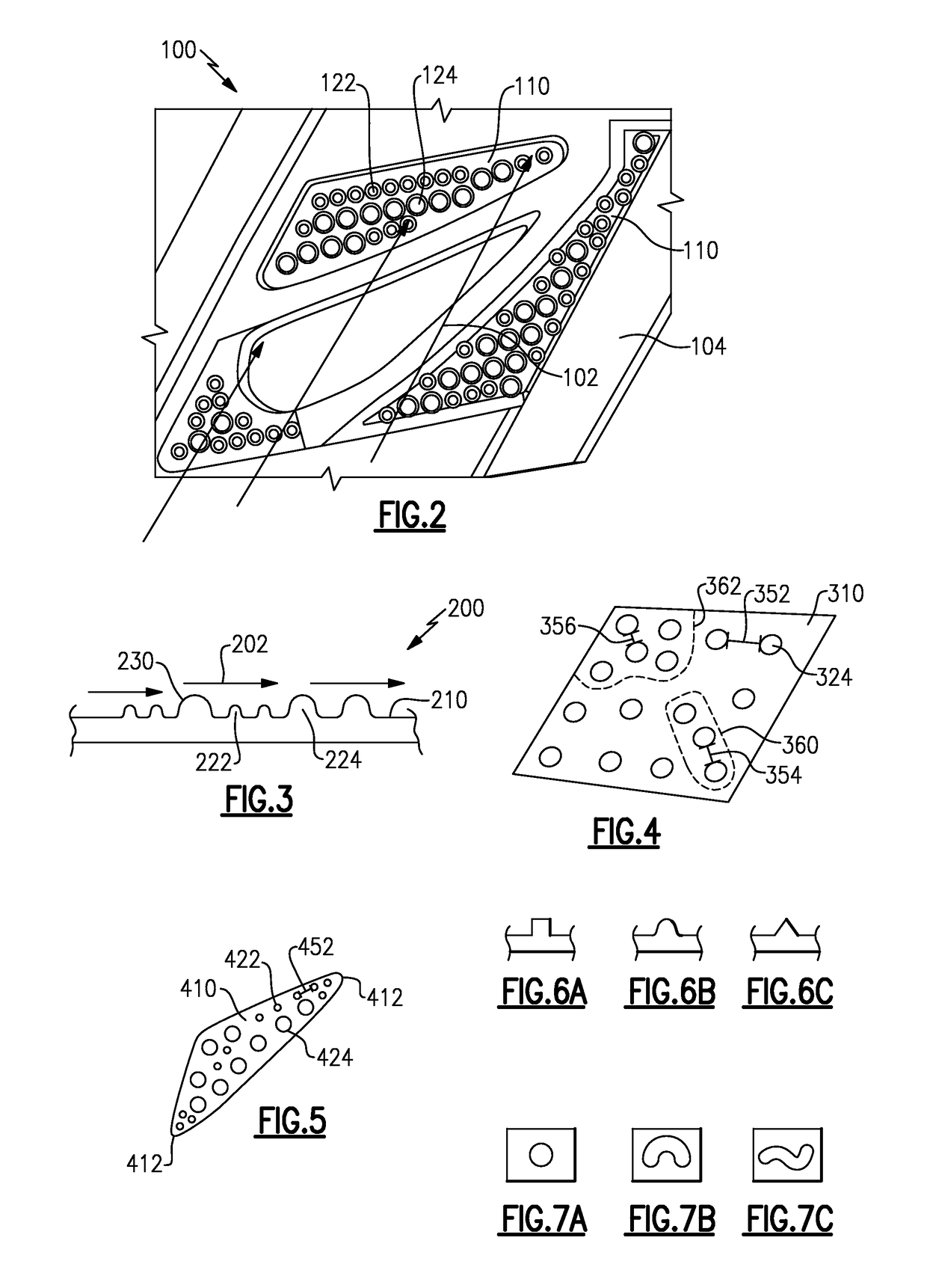
[0022]An exemplary method of enhancing cooling for a gas turbine engine component includes disposing a plurality of cooling nubs on a cooled surface according to a mixed pattern including at least one of multiple distinct sizes of cooling nubs, a varied concentration of cooling nubs, and a vari

Problems solved by technology

Components within gas turbine engines, such as aircraft engines, land based turbines, and the l

Method used


Image

  • Turbine component including mixed cooling nub feature
  • Turbine component including mixed cooling nub feature
  • Turbine component including mixed cooling nub feature

Examples


Example

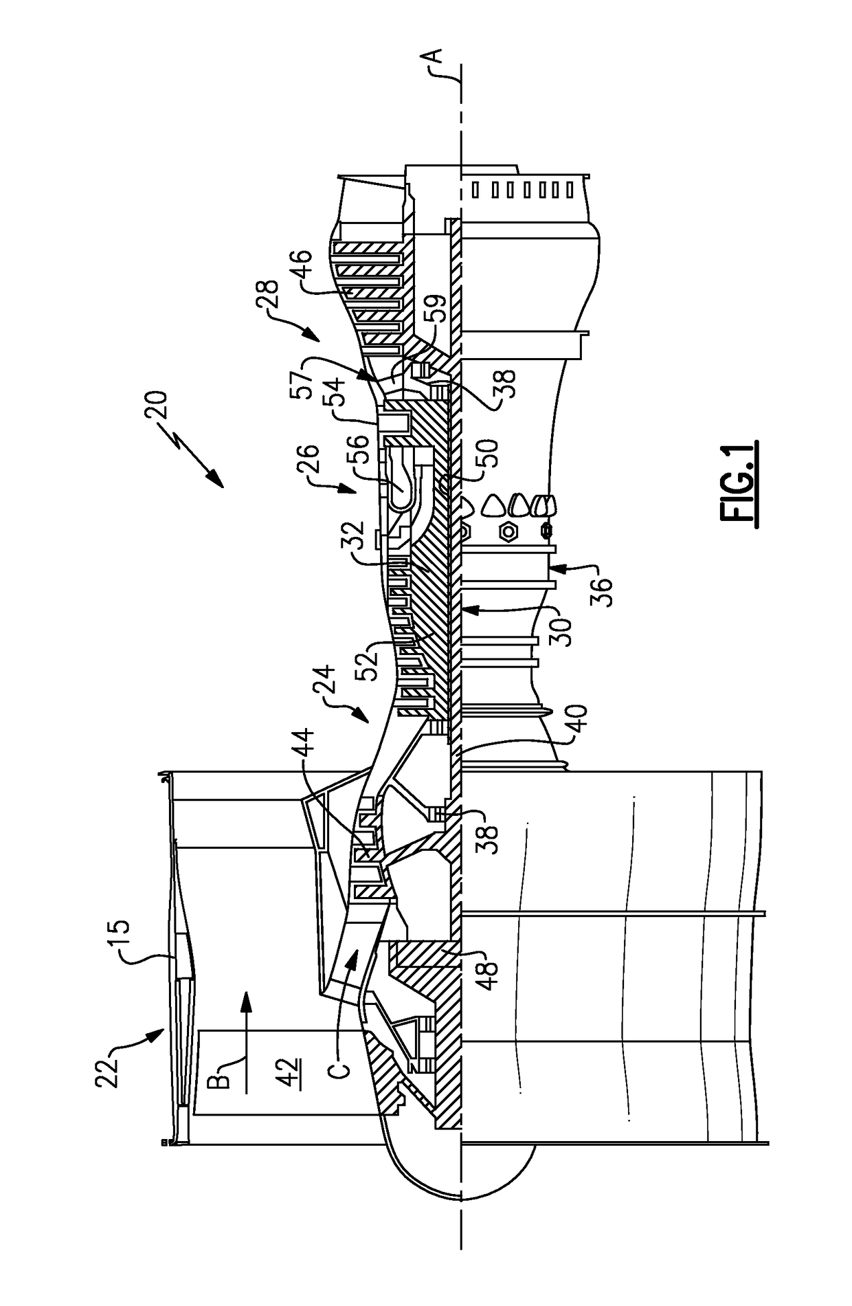
[0036]FIG. 1 schematically illustrates a gas turbine engine 20. The gas turbine engine 20 is disclosed herein as a two-spool turbofan that generally incorporates a fan section 22, a compressor section 24, a combustor section 26 and a turbine section 28. Alternative engines might include an augmentor section (not shown) among other systems or features. The fan section 22 drives air along a bypass flow path B in a bypass duct defined within a nacelle 15, while the compressor section 24 drives air along a core flow path C for compression and communication into the combustor section 26 then expansion through the turbine section 28. Although depicted as a two-spool turbofan gas turbine engine in the disclosed non-limiting embodiment, it should be understood that the concepts described herein are not limited to use with two-spool turbofans as the teachings may be applied to other types of turbine engines including three-spool architectures.

[0037]The exemplary engine 20 generally includes ...


PUM


Abstract

A component for a gas turbine engine includes at least one cooled surface configured to contact a cooling flow, the at least one cooled surface has a base surface and a plurality of cooling nubs disposed about the base surface. The plurality of cooling nubs are distributed about the base surface in a mixed pattern.

Description

TECHNICAL FIELD[0001]The present disclosure relates generally to cooling features for gas turbine engine components, and more specifically to a mixed cooling nub feature for the same.BACKGROUND[0002]Components within gas turbine engines, such as aircraft engines, land based turbines, and the like, are frequently exposed to high temperatures due to the operation of the gas turbine engine. In order to mitigate the effects of the high temperatures, some components are exposed to cooling flows and convective heat transfer from the component to the cooling flow cools the component.[0003]The cooling flow continuously cycles a coolant, such as air, over one or more surface of the component. The cycling of the coolant removes the warmed coolant and replaces the warmed coolant with a cooled coolant. In a closed loop coolant system, the warmed coolant is passed to a cooler, alternately referred to as a condenser, where it is cooled and returned to the coolant flow. In an open loop cooling sys...

Claims


Application Information

Patent Timeline
IPC IPC(8): F02C7/18
CPCF02C7/18F05D2250/28F05D2250/18F01D5/187F05D2240/81F05D2260/2214Y02T50/60F02C7/12
Inventor MCGINNIS, CHRISTINE F.MENTZ, KARL A.AUXIER, JAMES TISLEY
Owner RAYTHEON TECH CORP
Why Eureka
Try Eureka