Shock absorber apparatus

a technology of shock absorber and shock absorber, which is applied in the direction of shock absorber, spring/damper design characteristics, vibration dampers, etc., can solve the problems of poor shock absorber performance, often challenging shock absorber design, and still far from optimal

Inactive Publication Date: 2005-04-14
NOST TECH
View PDF18 Cites 81 Cited by
  • Summary
  • Abstract
  • Description
  • Claims
  • Application Information

AI Technical Summary

Benefits of technology

[0017] And another aspect of the invention relates to a shock absorber apparatus having a housing, and a cylinder bore enclosed by the housing, and having a longitudinal axis, and a rod having a first end and an opposite second end, and wherein the rod is substantially positioned concentric to, and along, the longitudinal axis of the cylinder bore, and wherein the first end of the rod is positioned within the cylinder bore, and a piston fastened concentrically to the rod, and movably positioned within the cylinder bore, and a step washer positioned concentrically around the rod in stacking relation, and positioned proximate to the piston, and a pressure plate positioned concentrically around the step washer in sliding relation, and a plate spring positioned concentrically around the rod so that it is borne by the step washer, and further wherein a portion of the plate spring is held in tension by the pressure plate.

Problems solved by technology

The design of the shock absorber has often been challenging due to the nature of the dynamic motion of a vehicle as it travels over widely varying terrain and driving conditions.
Shock absorber performance, though improved over the last few decades, is still far from optimum.
Often, the constraints and criteria used in the design of a shock absorber are counter to one another, and force the designer to balance tradeoffs.
The result is a shock absorber having performance that often delivers compromising results.
In certain applications, shock absorber systems are taken to extremes, providing even further challenges for the designer.
However, many shock absorber systems available on the market today have a limited tuning capability.
Further, those with an adjusting or tuning capability, are often difficult to adjust, resulting in mal-adjustments of the shock absorber which degrades the performance even further.
The rough and choppy terrain will cause instantaneous jarring reaction forces on the shock absorber.
Unfortunately, up to this point, it has been difficult to realize a shock absorber, having a suitable response for the varying types of terrain cited above.
Unfortunately, while such attempts improve the performance, they also add cost and weight to the vehicle.

Method used


Image

  • Shock absorber apparatus
  • Shock absorber apparatus
  • Shock absorber apparatus

Examples


Embodiment Construction

[0079] This disclosure of the invention is submitted in furtherance of the constitutional purposes of the U.S. Patent Laws “to promote the progress of science and useful arts” (Article 1, Section 8).

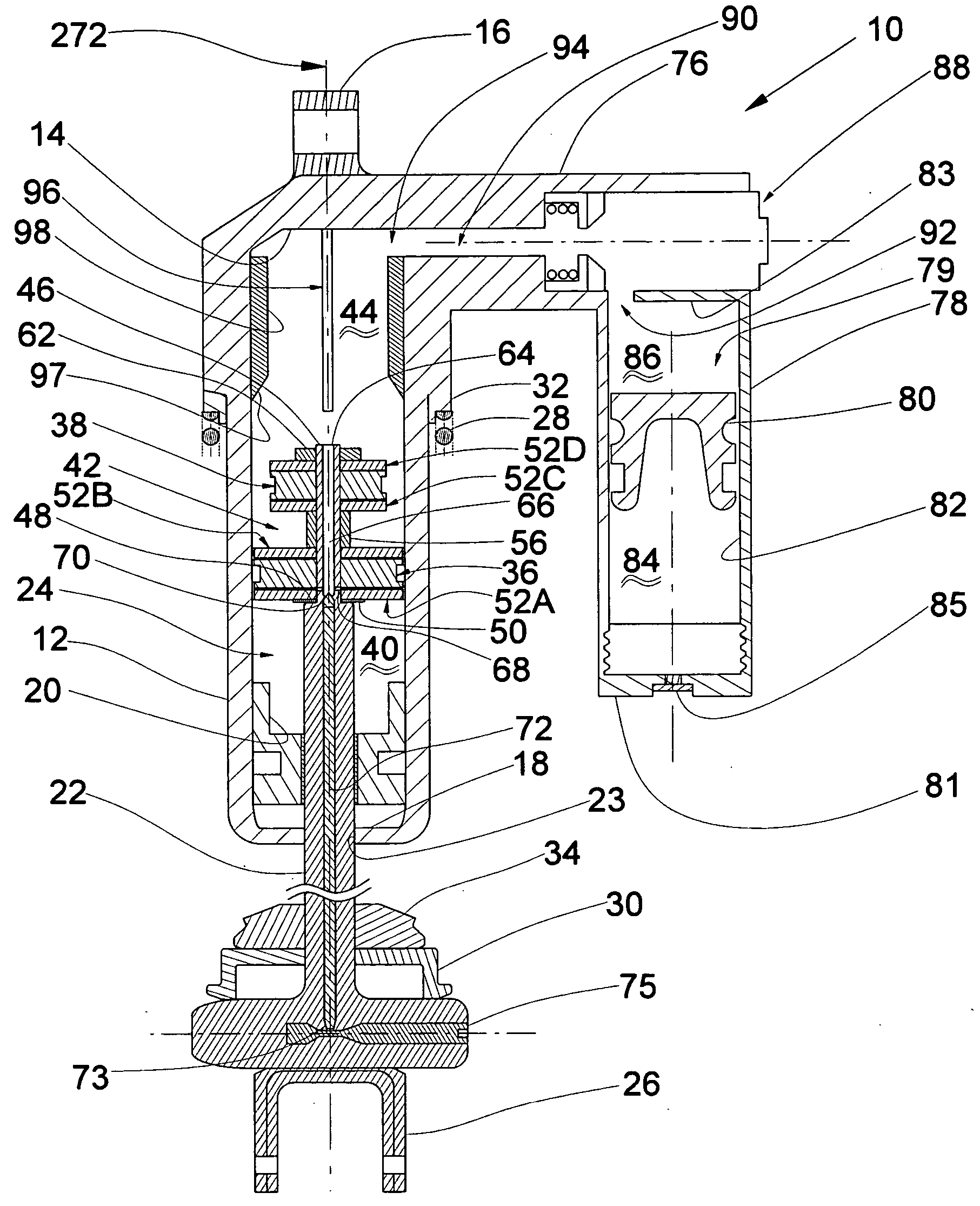
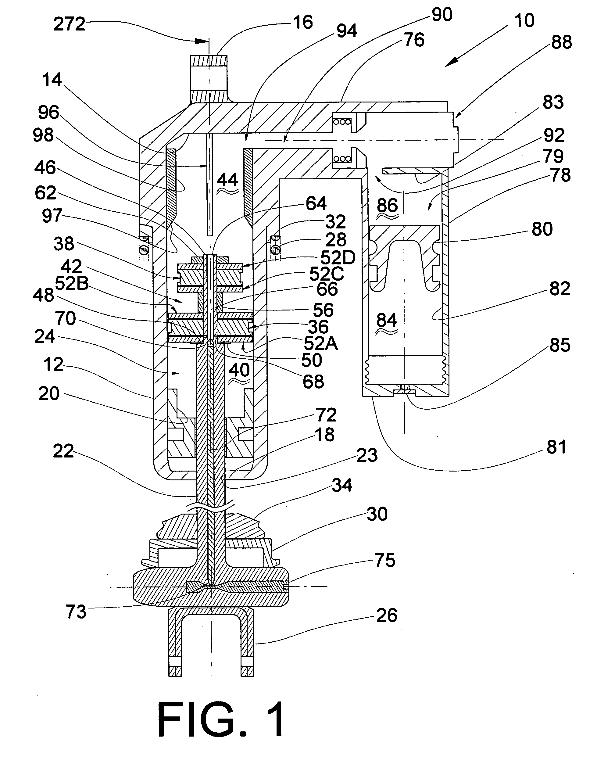
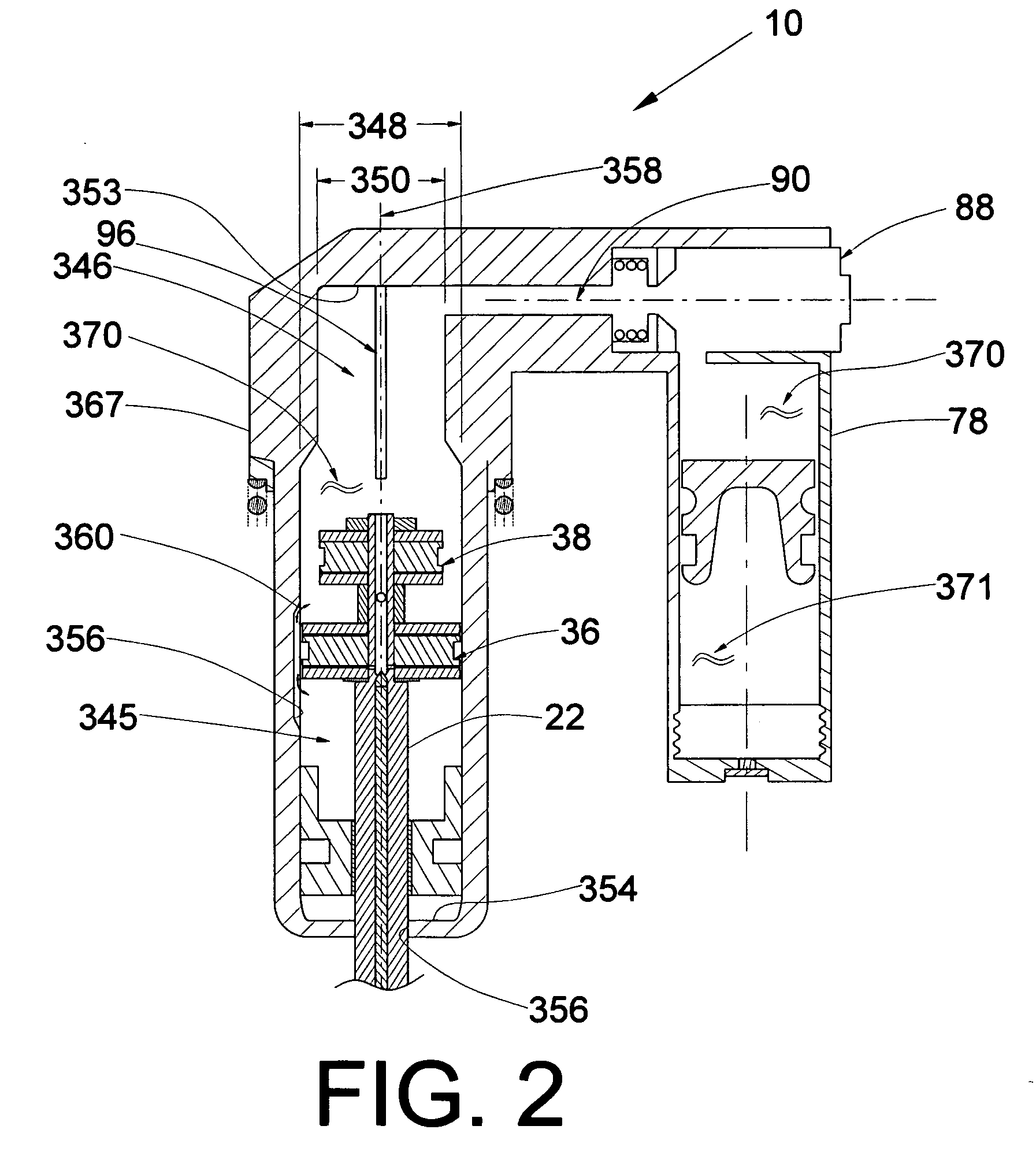
[0080] Referring to FIG. 1, an exemplary shock absorber constructed in accordance with an embodiment of the invention is identified generally by the reference numeral 10. The shock absorber 10 is designed to be positioned between a vehicle chassis (not shown), and a wheel-carrying hub (not shown) in a manner known in the art. The suspension unit 10 includes a cylinder assembly or housing 12 which is provided with a first end wall or cap 14. The end wall 14 carries a bracket 16 so as to provide a pivotal connection to the vehicle chassis (not shown).

[0081] The cylinder housing 12 having a longitudinal axis 272 includes a cylinder bore 24 that is closed at one end by the end wall 14 and at the other end by the gland 20. The opposite end of the cylinder housing 12 is enclosed by an end wa...


PUM


Abstract

A shock absorber apparatus includes a response adjustment mechanism connected in fluid transmission relation between a first cylinder and a second cylinder that is configured to provide three or more adjustments for tuning the response of the shock absorber system. The shock absorber may also include a damping valve assembly which may include a step washer positioned concentrically around a piston rod, and in stacking relation, and may be further positioned proximate to a piston. The damping valve assembly may also include a pressure plate positioned concentrically around the step washer in sliding relation, and a plate spring positioned concentrically around the rod so that the plate spring is borne by the step washer and a portion of the plate spring is held in tension by the pressure plate.

Description

CROSS REFERENCE TO RELATED APPLICATIONS [0001] This application relates to and claims priority to U.S. Provisional Application 60 / 509,833 filed on Oct. 8, 2003 and claims priority to U.S. Provisional Application 60 / 537,429 filed on Jan. 15, 2004.BACKGROUND OF THE INVENTION [0002] 1. Field of the Invention [0003] This invention relates to a shock absorber, and more particularly to a shock absorber incorporating improved dampening response mechanisms and more specifically to a shock absorber having a versatile adjustable response mechanism for tuning the performance of the shock absorber apparatus. [0004] 2. Description of Related Art [0005] Shock absorber systems have been in use for damping the reaction forces experienced with wheeled vehicles throughout the use of the wheel as a means of transport. Shock absorbers are well known in the art and have been used successfully for many years to improve the safety and handling of many types of vehicles. The design of the shock absorber ha...

Claims


Application Information

Patent Timeline
Patent Type & Authority Applications(United States)
IPC IPC(8): F16F9/096F16F9/342F16F9/46F16F9/48
CPCF16F9/065F16F9/342F16F2230/42F16F9/486F16F9/466F16F9/49F16F9/3488
Inventor RUSSELL, PETER
Owner NOST TECH
Why Eureka
Try Eureka