Tray with flat bottom reference surface

Inactive Publication Date: 2005-04-14
PEAK PLASTIC & METAL PRODS INT
View PDF9 Cites 7 Cited by
  • Summary
  • Abstract
  • Description
  • Claims
  • Application Information

AI Technical Summary

Benefits of technology

[0007] It is an advantage of this invention in that it prov

Problems solved by technology

Part ejection is a forceful process, and the pressure of the pins on the tray leaves burrs/marks/blemishes on the tray surfaces.
These burrs cause variations in the effective tray thickness and as a result trays cannot be stacked with a consistent height or degree of flatness.
The burrs cause errors in calibration of automated tray handling equipment, and equipment for picking and placing components in tray component pockets.
Removal of burrs woul

Method used


Image

  • Tray with flat bottom reference surface
  • Tray with flat bottom reference surface
  • Tray with flat bottom reference surface

Examples


Embodiment Construction

[0020] While the present invention will be described herein with reference to particular embodiments thereof, a latitude of modifications, various changes and substitutions are intended, and it will be appreciated that in some instances some features of the invention will be employed without a corresponding use of other features without departing from the spirit and scope of the invention as described with respect to the preferred embodiments set forth herein.

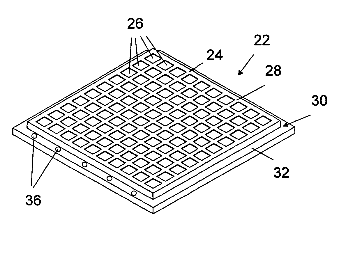
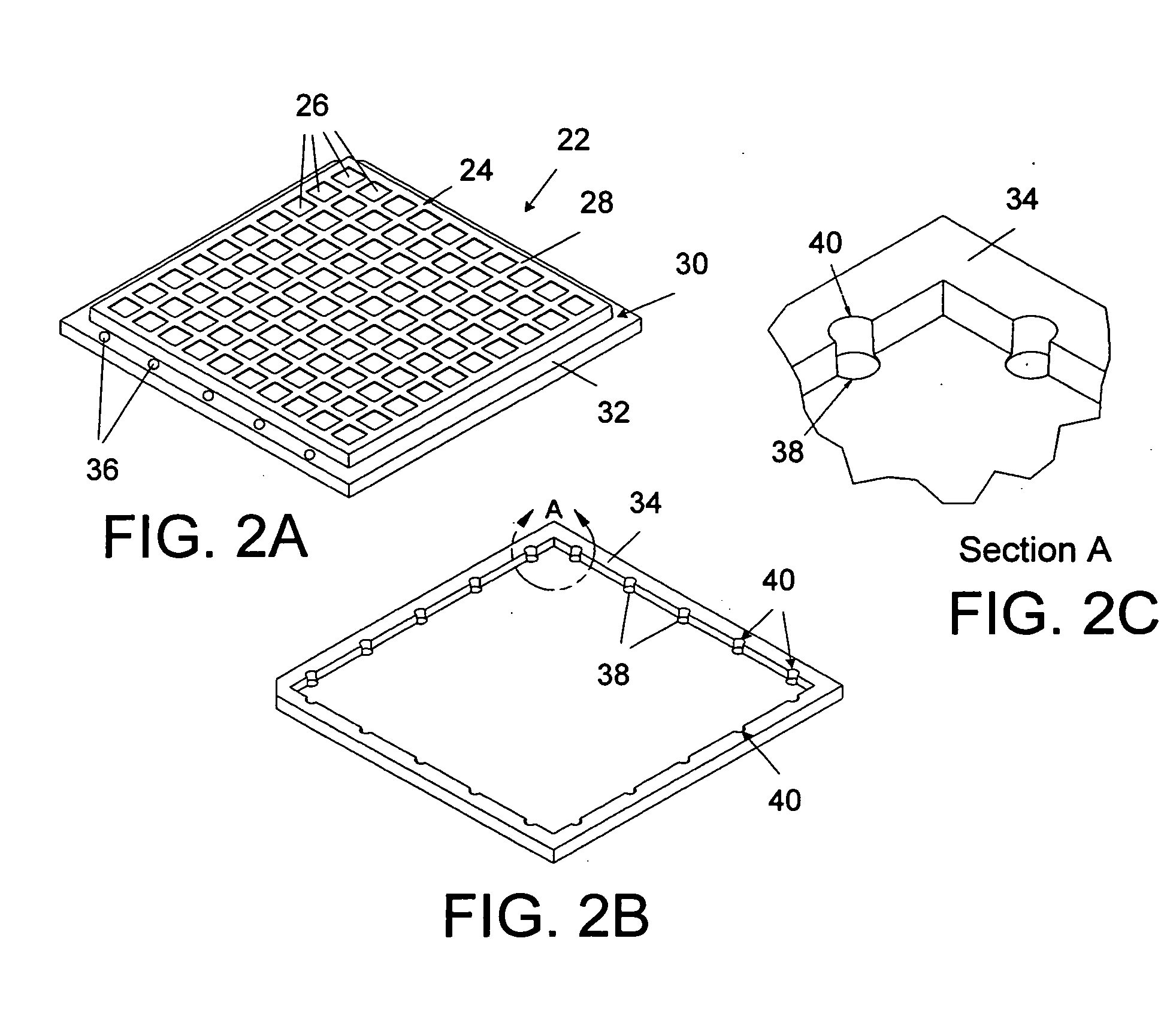
[0021] Referring now to FIGS. 2A and 2B, a component tray 22 is shown that has been formed in a mold. The tray 22 has a component housing portion 24, containing a plurality of component pockets 26 opening to top surface 28. The component pockets 26 are for holding small components, such as semiconductor devices. A flange 30 extends around the housing portion 24, defining the perimeter of the tray 22. The flange 30 has a flange top surface 32, and a bottom surface 34 shown in FIG. 2B. The flange alternatively can be of other co...


PUM


Abstract

A molded component tray includes a component housing portion having a plurality of component pockets. The tray has a flange around the component housing portion defining a perimeter of the tray. A flange top surface in one embodiment is below the component housing top surface. A flange bottom surface includes recessed areas positioned in alignment with mold ejector pins which may contact the flange bottom surface, and alternatively in alignment with mold ejector pin marks on the flange top surface. The depth of the recesses is greater than the height burrs left by the ejector pins, thereby leaving the tray bottom surface free of burrs caused by ejector pins. Alternatively, when one tray is stacked on top of another, the recesses in the bottom of an upper tray can be positioned to allow clearance for ejector pin marks on the top of the flange of a lower tray.

Description

RELATED APPLICATIONS [0001] This application is related to U.S. Application entitled Bare Die Tray With Flat Datum Surface filed on the same date as this application, bearing attorney reference 0678100301344 which is expressly incorporated by reference herein.BACKGROUND OF THE INVENTION [0002] 1. Field of the Invention [0003] This invention relates to trays for use in carrying components such as semiconductors, and more particularly to a tray having flat datum surfaces and configured to avoid calibration variations due to mold injector pin burrs imposed on the tray during manufacture. [0004] 2. Description of the Related Art [0005] Small components such as semiconductors are often stored or shipped in molded plastic trays similar to tray 10 shown in FIGS. 1A and 1B. In the molding production operation, ejector pins are used to push / eject the tray from the mold casing. Burrs are caused from molten plastic filling the circumferential gap between the ejector pin and the ejector pin hol...

Claims


Application Information

Patent Timeline
IPC IPC(8): B65D1/36H01L21/673
CPCH01L21/67333B65D1/36
Inventor PYLANT, JAMES D.BRADLEY, SCOTT C.
Owner PEAK PLASTIC & METAL PRODS INT
Why Eureka
Try Eureka