Chassis structure for vehicles

a chassis and chassis technology, applied in the direction of roofs, transportation and packaging, vehicle arrangements, etc., can solve the problem of insufficient utilization of crushable zones of size members, and achieve the effect of effective absorption of impa

Active Publication Date: 2005-04-14
MITSUBISHI MOTORS CORP
View PDF12 Cites 28 Cited by
  • Summary
  • Abstract
  • Description
  • Claims
  • Application Information

AI Technical Summary

Benefits of technology

[0008] The present invention has been developed in light of the above problem, and aims to provide a chassis structure capable of effectively absorbing an impact exerted from the front.
[0013] The chassis structure of the invention is constructed such that when a significant impact is exerted on the cross member upon a collision, the cross member is detached from the side members. Accordingly, the buckling motion of the side members is not interrupted by the cross member, therefore the side members can sufficiently absorb the impact.
[0032] The reinforcing member attached to each side member enables an impact to be effectively transmitted to the support unit to thereby accelerate the deformation or breakage of the support unit.

Problems solved by technology

Thus, the cross member interrupts the buckling of the side members, which means that the crushable zone of the size members is not sufficiently utilized.

Method used


Image

  • Chassis structure for vehicles
  • Chassis structure for vehicles
  • Chassis structure for vehicles

Examples


embodiment 1

[0050] Referring first to FIGS. 1 to 8, a chassis structure for vehicles according to a first embodiment of the invention will be described.

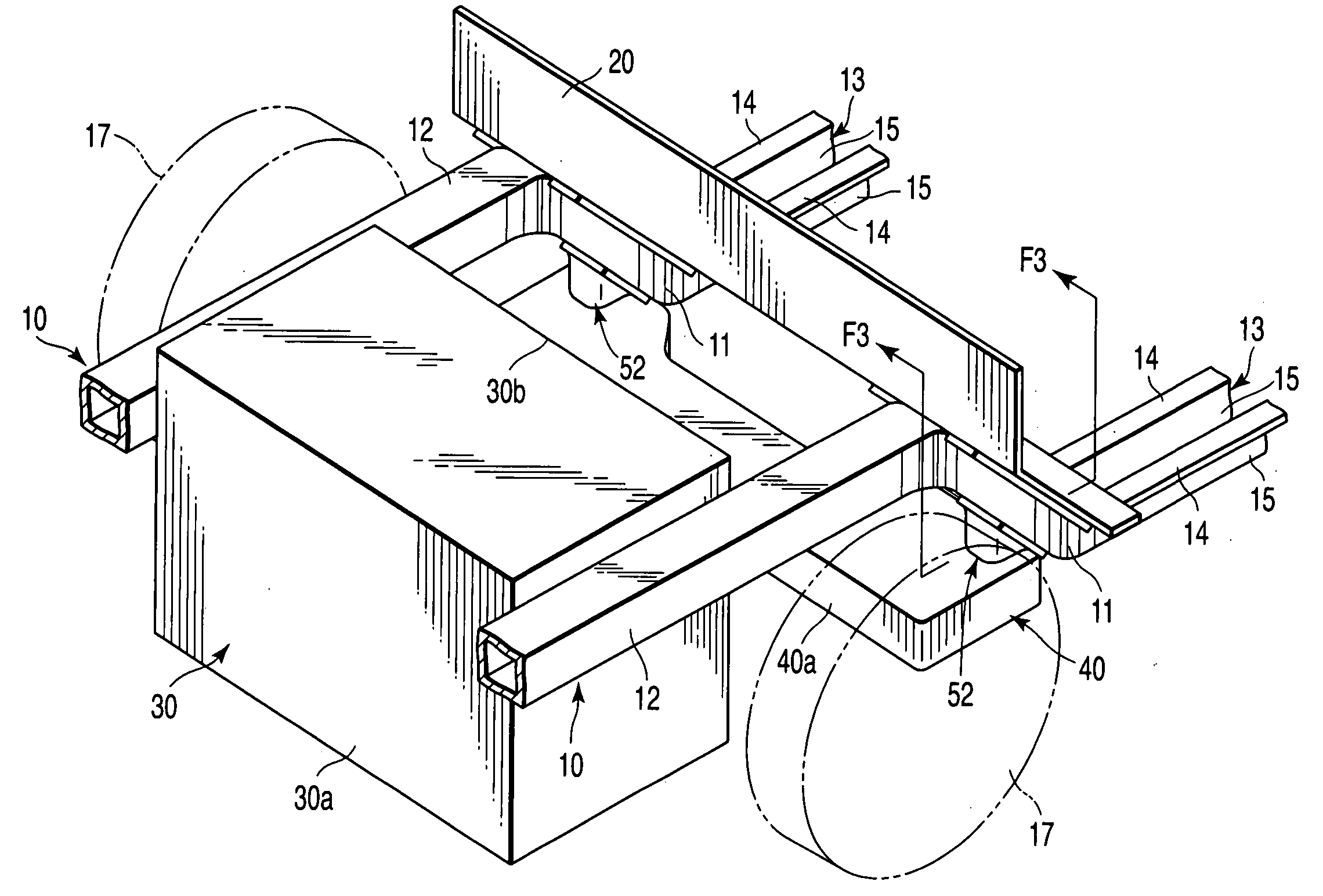
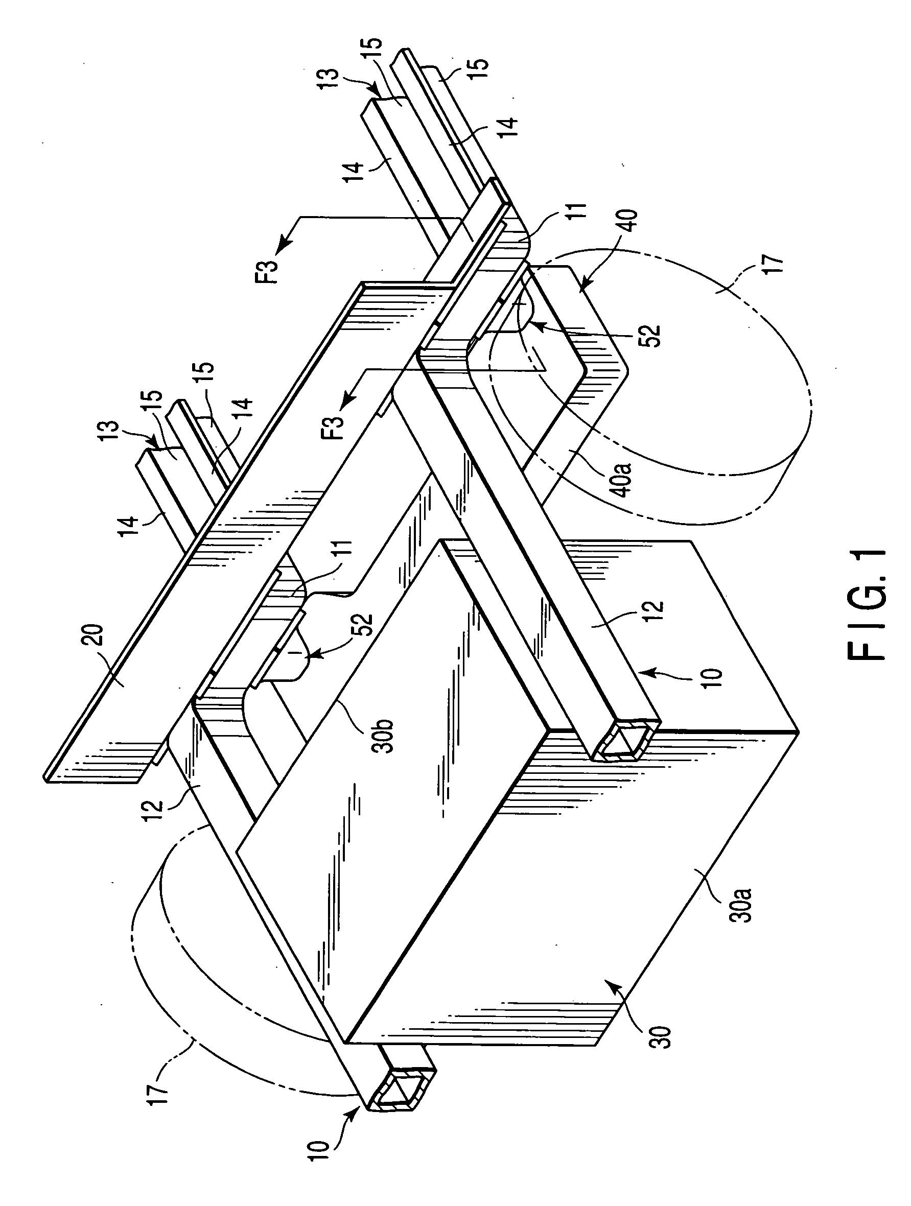
[0051]FIG. 1 shows the front portion of a chassis structure for, for example, front-engine front-wheel-drive (FF) vehicles according to the first embodiment. In FIG. 1, reference 10 denotes side members extending in the longitudinal direction of a vehicle body. A dashboard 20 is extended between and secured to the side members 10. The side members 10 each have a slanting portion 11 backwardly lowered, on which the dashboard 20 is mounted. The portion of each side member 10 located before the slanting portion 11 will hereinafter be referred to as “the front portion 12”, while the portion of each side member 10 located behind the slanting portion 11 will hereinafter be referred to as “the rear portion 13”.

[0052] The front portion 12 has, for example, a substantially rectangular cross section, and is arranged to buckle upon receiving an impact ex...

second embodiment

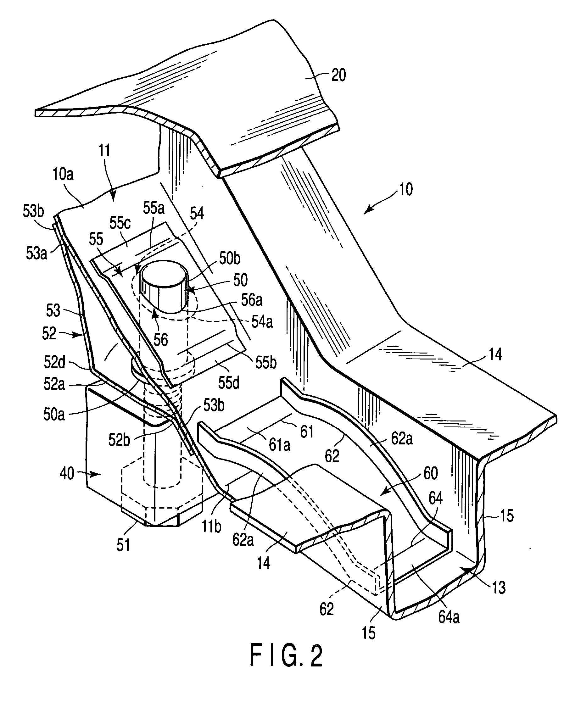
[0077]FIG. 9 shows part of a chassis structure according to a second embodiment of the invention. Specifically, FIG. 9 shows a structure in which the coupling rod 50 is supported by a side member 10. The other structures are similar to those of the first embodiment, therefore no description is given thereof. Further, elements similar to those of the first embodiment are denoted by corresponding reference numerals, and are not described.

[0078] In the second embodiment, the upper portion 50b of the coupling rod 50 is supported by a second support plate 70 in the shape of a bulk head, as shown in FIG. 9. The second support plate 70 is arranged across the center of the through hole 54 in the width direction of the vehicle body, and is in contact with the upper surface of the bottom 10a of the slanting portion 11 of the side member 10, and with the inner surfaces of the side walls 15 of the side member 10. The lower end 70a of the second support plate 70 includes a flange 71 backwardly ...


PUM


Abstract

It is an object of the invention to provide a chassis structure for vehicles that can effectively absorb an impact. Side members extend in a longitudinal direction of a vehicle body along the sides of the vehicle body. The side members are made to buckle in the longitudinal direction upon receiving an impact. A cross member extends between the side members along the width direction of the vehicle body. Coupling rods are supported by the side members via support members. The cross member is fixed to tips of the coupling rods by bolts. When an impact exceeding a predetermined level is exerted on the cross member in the longitudinal direction, the support members are broken, whereby the cross member and coupling rods are detached from the side members.

Description

CROSS-REFERENCE TO RELATED APPLICATIONS [0001] This application is based upon and claims the benefit of priority from prior Japanese Patent Application No. 2003-349917, filed Oct. 8, 2003, the entire contents of which are incorporated herein by reference.BACKGROUND OF THE INVENTION [0002] 1. Field of the Invention [0003] The present invention relates to a chassis structure for vehicles, and more particularly to a structure in which a cross member is attached to side members that provide part of a chassis. [0004] 2. Description of the Related Art [0005] In vehicles, there is a demand for effective reduction of an impact exerted thereon when a collision occurs. To absorb an impact exerted on a vehicle from the front, for example, the front portions of side members, which are included in the chassis of the vehicle and extend in the longitudinal direction of the vehicle, are designed to easily buckle upon receiving the impact. This buckling portion is called a crushable zone. [0006] Fur...

Claims


Application Information

Patent Timeline
Patent Type & Authority Applications(United States)
IPC IPC(8): B62D25/20B62D21/00B62D21/15B62D25/08
CPCB62D25/082B62D21/152
Inventor TOMITA, TATSUZO
Owner MITSUBISHI MOTORS CORP
Why Eureka
Try Eureka