Liquid crystal display device and electronic apparatus

a display device and liquid crystal technology, applied in the direction of liquid crystal compositions, chemistry apparatus and processes, instruments, etc., can solve the problems of reducing the degree of freedom of optical design, spotted pattern generation, narrow viewing angle of transmissive display, etc., to achieve wide viewing angle, suppress display defects, and good display characteristics

Active Publication Date: 2005-04-14
BOE TECH GRP CO LTD
View PDF3 Cites 11 Cited by
  • Summary
  • Abstract
  • Description
  • Claims
  • Application Information

AI Technical Summary

Benefits of technology

[0030] Next, the electronic apparatus of the present invention comprises the aforementioned liquid crystal display device. Accordingly, it is possible to suppress display defe...

Problems solved by technology

In the related transflective liquid crystal display device, there can be a problem in that a viewing angle in the transmissive display is narrow.
This problem is involved in the limitation that a transflective plate is provided in the inner surface of the liquid crystal cell in order to prevent parallax, and thus, the reflective display is performed with only one polarizing plate provided on observer's side, so that the degree of freedom in an optical design is lowered.
In addition, since the ali...

Method used


Image

  • Liquid crystal display device and electronic apparatus
  • Liquid crystal display device and electronic apparatus
  • Liquid crystal display device and electronic apparatus

Examples


third embodiment

[0073] As shown in FIG. 6, in the liquid crystal display device 300 the convex portion 26a formed in the transmissive display region T and the insulating film 26 as a liquid-crystal-layer thickness-adjusting layer are formed in the same process, so that the convex portion 26a formed in the transmissive display region T is formed on the same layer with the same material as the insulating film 26.

[0074] In other words, resin layers having predetermined patterns are formed on the reflective display region R and the transmissive display region T. The resin layer on the reflective display region R is used as the insulating film 26 which is a liquid crystal thickness adjusting layer, and the resin layer on the transmissive display region T is used as the convex portion 26a for providing a convex shape to a sandwiching surface of the liquid crystal layer 50 in the transmissive display region T. In addition, a slit may be simultaneously formed in the electrode on the convex portion 26a in ...

first embodiment

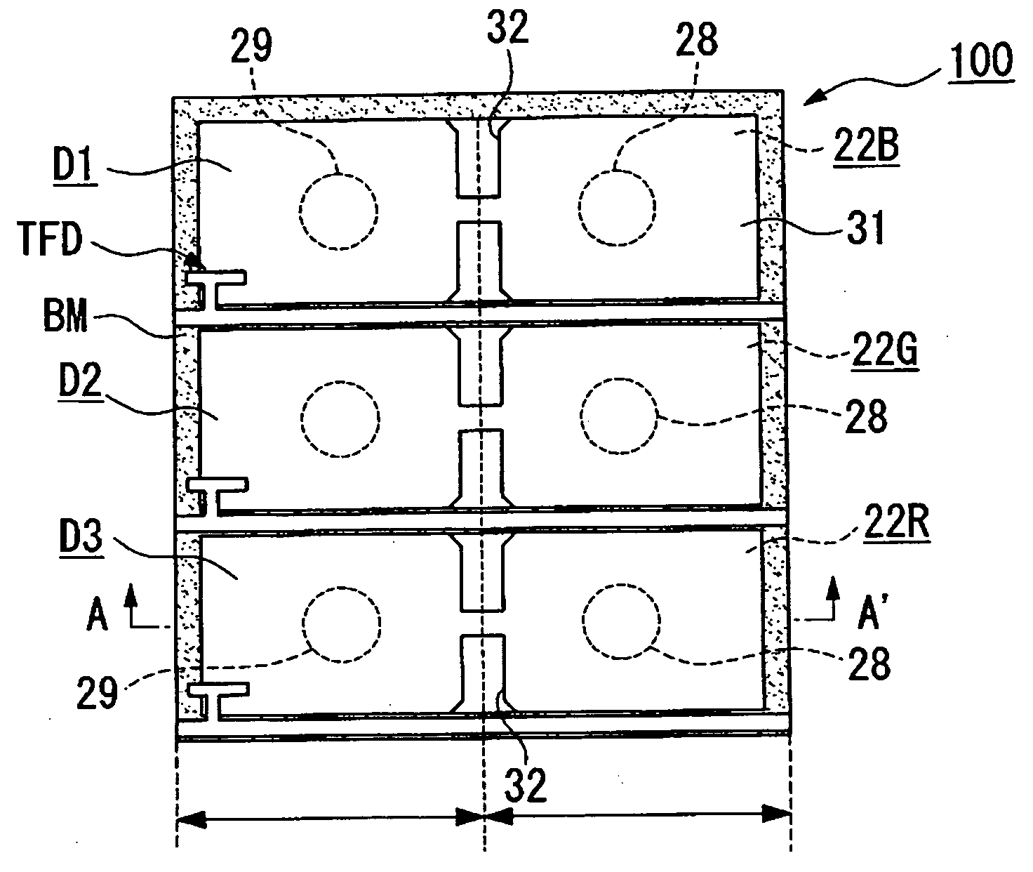
[0081] Similarly, other examples of the liquid crystal display device 100 are constructed with the following conditions. The thickness of the liquid crystal layer in the transmissive display region T is 4.0 μm, the thickness of the liquid crystal layer in the reflective display region R is 2.0 μm, and the height of the convex portion 28 is 1.5 μm. On the inner surface of the lower substrate 10, the slit 29 or convex portion (instead of the slit) is formed in the reflective display region R. Various widths of the convex portion or the slit are selected. Then, contrasts in the reflective display of the examples evaluated are compared. The result of the comparison is shown in Table 2 as follows.

TABLE 2Width of convex portion or slit5 μm8 μm12 μmWhen the convex portion is formed in the9.68.76.8transmissive display regionWhen the slit is formed in the transmissive16.715.614.3display region

[0082] As shown in the table, it can be understood that, the spotted pattern are not detected in al...


PUM


Abstract

Aspects of the invention can provide a transflective liquid crystal display device of vertical alignment mode capable of suitably controlling the direction that liquid crystal molecules are tilted. The liquid crystal display device can include a liquid crystal layer interposed between a pair of substrate and transmissive and reflective display regions in each dot region. An insulating film for varying the thickness of the liquid crystal layer in the reflective and transmissive display regions is provided. On a substrate having the insulating film formed thereon, an electrode slit for controlling the alignment of the liquid crystal molecules can be formed in the reflective display region. Similarly, a convex portion for controlling the alignment of the liquid crystal molecules can be formed in the transmissive display region.

Description

BACKGROUND OF THE INVENTION [0001] 1. Field of Invention [0002] The present invention relates to a liquid crystal display device and an electronic apparatus, and more particularly, to a liquid crystal display device using vertical alignment type liquid crystals. [0003] 2. Description of Related Art [0004] Related liquid display device can include a transflective liquid crystal display device operated in alignment direction, when a voltage is applied, of the liquid crystal molecule reflective and transmissive modes. As such a transflective liquid crystal display device, there has been proposed a transflective liquid crystal display device in which a liquid crystal layer is interposed between upper and lower substrates, a reflecting film made of metal, such as aluminum where light-transmitting window is formed, for example, is provided on an inner surface of the lower substrate, and the reflecting film also serves as a transflective plate. In this case, in the reflective mode, externa...

Claims


Application Information

Patent Timeline
IPC IPC(8): G02F1/1337G02F1/1333G02F1/1335G02F1/1343G02F1/139
CPCG02F1/133371G02F1/1393G02F1/133707G02F1/133555G02F1/1337G02F1/1343
Inventor HIGA, MASAKATSU
Owner BOE TECH GRP CO LTD
Why Eureka
Try Eureka