Projector and method of correcting projected image distortion

a projector and image technology, applied in the field of projector and image correction method, can solve the problems of low image quality of smaller images and often limited projectors, and achieve the effect of increasing the freedom of installation position and reducing image quality degradation

Active Publication Date: 2005-04-14
SHARP NEC DISPLAY SOLUTIONS LTD
View PDF2 Cites 31 Cited by
  • Summary
  • Abstract
  • Description
  • Claims
  • Application Information

AI Technical Summary

Benefits of technology

[0011] It is therefore an object of the present invention to provide a projector which is capable of increasing the freedom of an installed position for the projector with respect to the position of the screen and of reducing a degradation of the image quality of images that are corrected by a distortion correcting circuit.
[0013] With the projector according to the present invention, since the distortion correcting means keeps the corrected image in a maximum size within the projection range of the projected image, any reduction in the image quality due to a contraction of the corrected image can be suppressed. As the distortion correcting means performs the above correcting process, the corrected image is obtained satisfactorily even if the projection optical axis is inclined at a relatively large angle of tilt to the projection surface. Consequently, a large allowable range is available for the angle of tilt of the projection optical axis with respect to the projection surface, allowing the projector to be installed in positions with increased freedom.

Problems solved by technology

Projectors are often limited to certain installed positions depending on the environment in which they are used, and occasionally have their projection optical axis inclined to the projection surface such as a screen or the like.
However, since image distortions are corrected by the distortion correcting circuit, corrected images are inevitably made smaller than images prior to being corrected, and the image quality of smaller images is low.

Method used


Image

  • Projector and method of correcting projected image distortion
  • Projector and method of correcting projected image distortion
  • Projector and method of correcting projected image distortion

Examples


Embodiment Construction

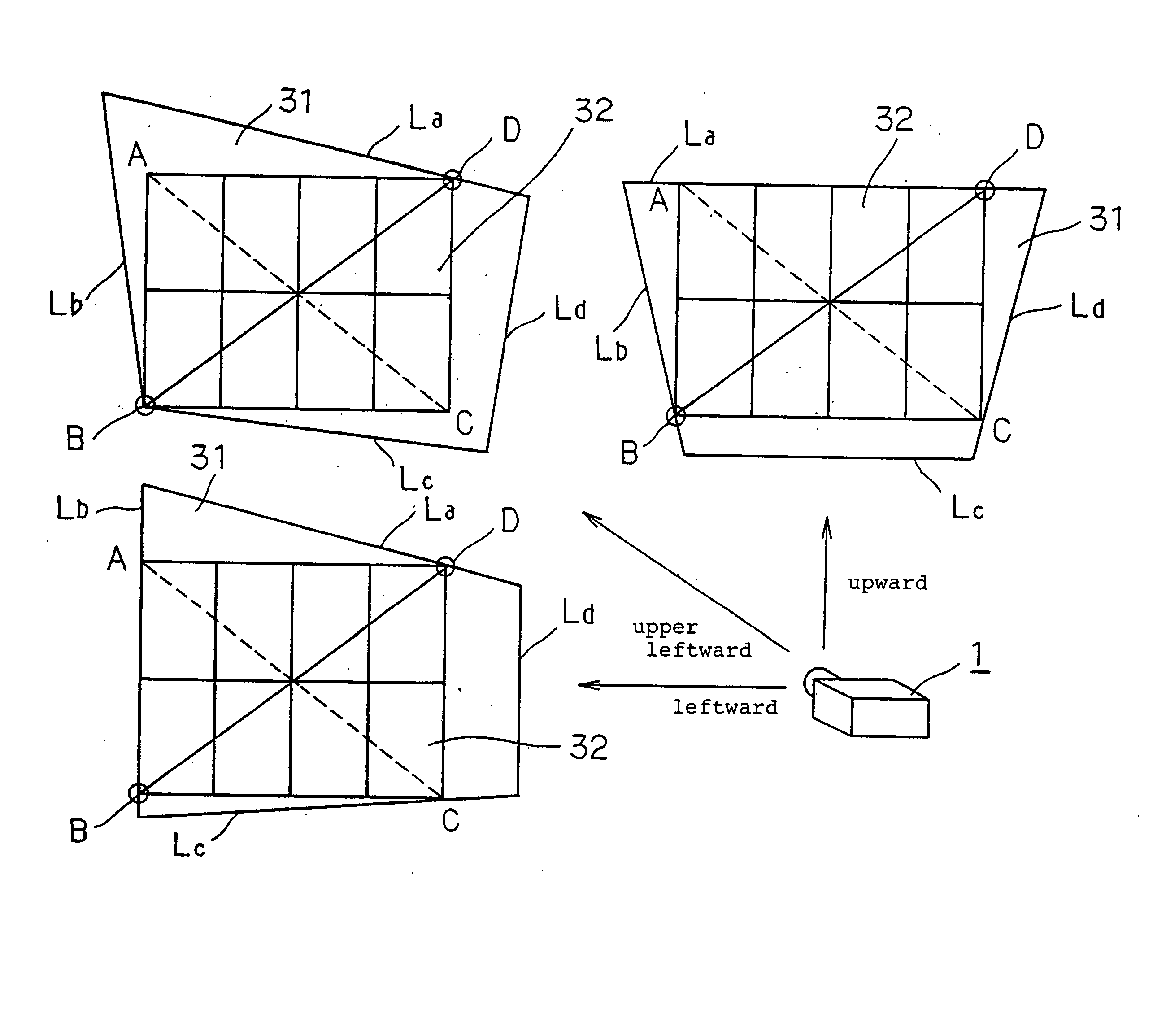
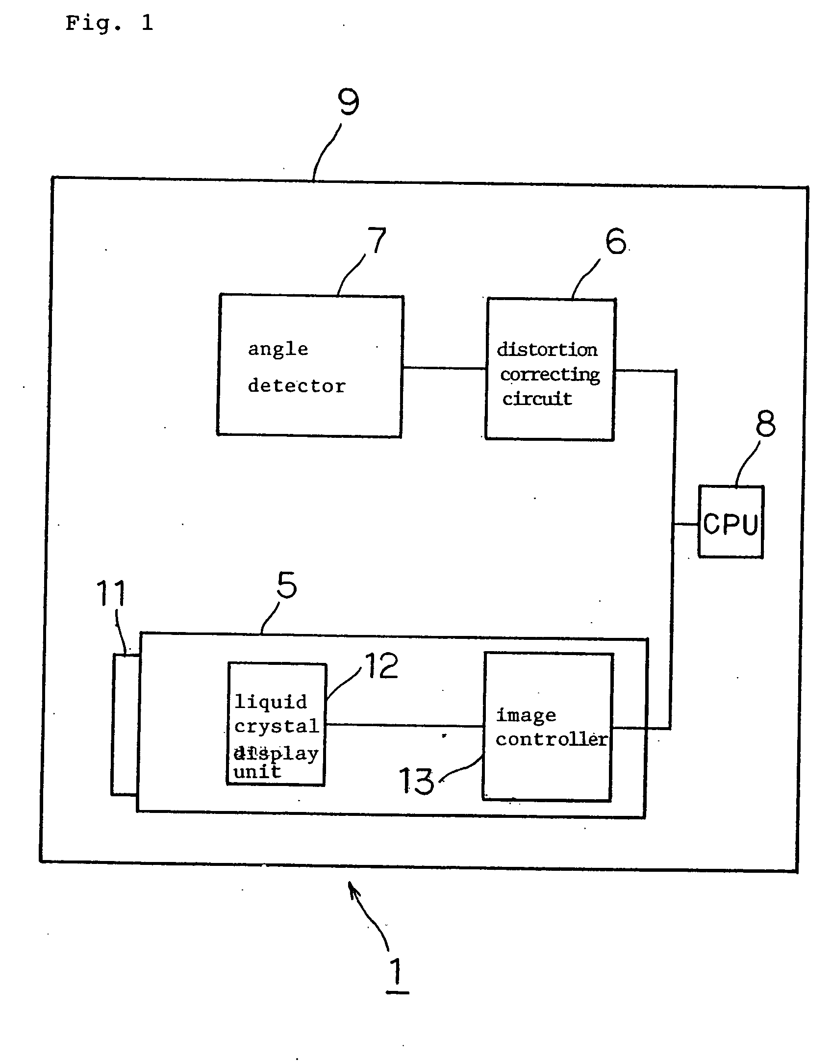
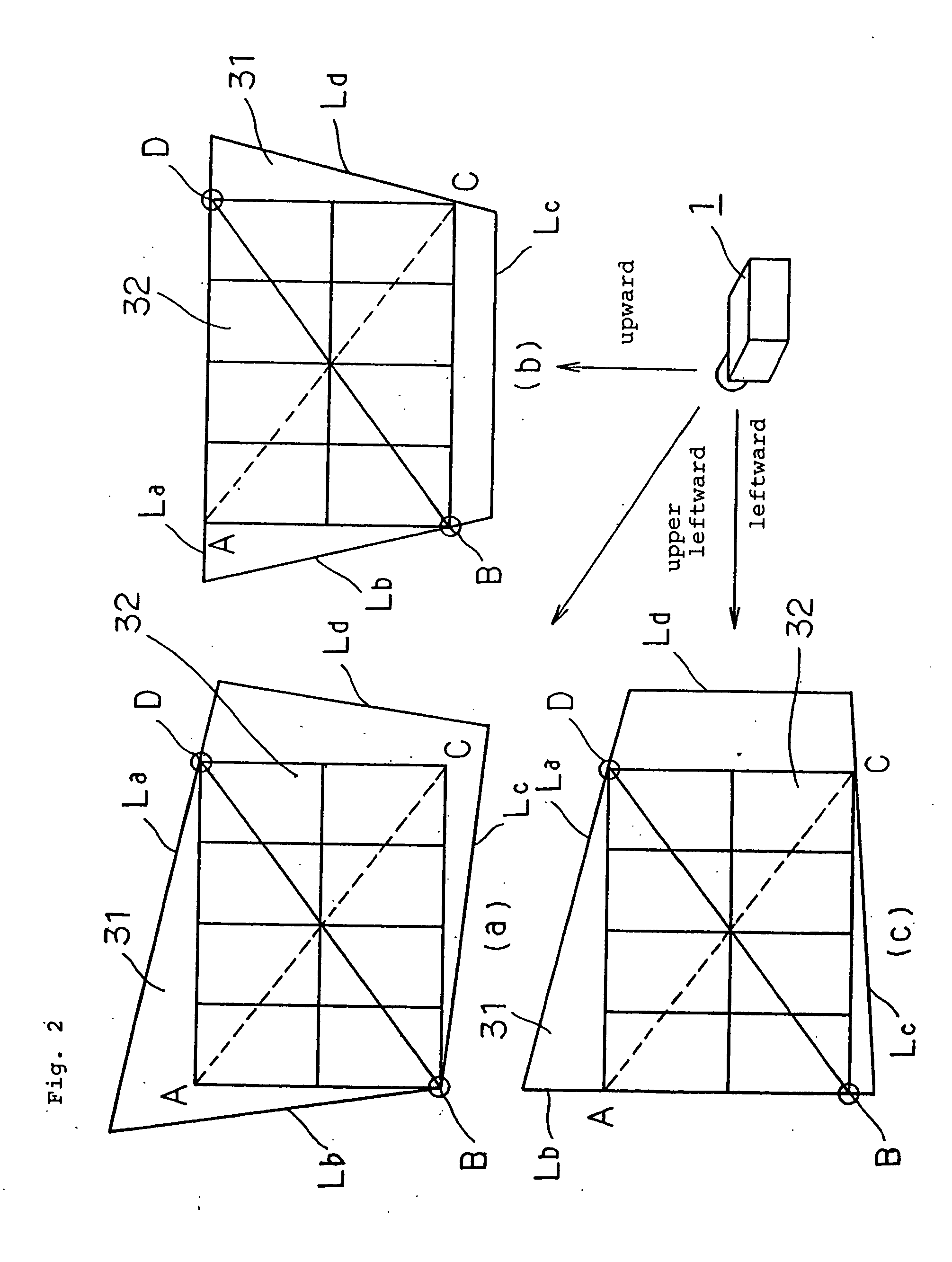
[0024] As shown in FIG. 1, projector 1 according to the present invention comprises projection device 5 having projection lens 11 for projecting an image onto a projection surface such as a screen or the like, distortion correcting circuit 6 as a distortion correcting means for correcting a distortion of an image to be projected onto the projection surface, angle detector 7 for detecting an angle of tilt of a projection optical axis with respect to the projection surface, CPU (Central Processing Unit) 8 for controlling projection device 5 and distortion correcting circuit 6, and housing 9 covering projection device 5, distortion correcting circuit 6, angle detector 7, and CPU 8.

[0025] Projection device 5 has, in addition to projection lens 11, liquid crystal display unit 12 for displaying an image to be projected, and image controller 13 for controlling an image to be displayed by liquid crystal display unit 12.

[0026] Distortion correcting circuit 6 performs an image deforming pro...


PUM


Abstract

A projector has a distortion correcting circuit for correcting a distorted quadrangular projected image, which is projected onto a projection surface along a projection optical axis inclined in at least one of leftward, rightward, upward, and downward directions, into a rectangular corrected image, such that one of the vertexes B, D on the opposite ends of either one of two diagonal lines of the rectangular corrected image is positioned on one side La of the outer edge of a projection range of the projected image and the other vertex on another side Lb that is positioned adjacent to the one side La.

Description

BACKGROUND OF THE INVENTION [0001] 1. Field of the Invention [0002] The present invention relates to a projector for projecting an image on a projection surface such as a screen or the like and a method of projecting an image, and more particularly a projector for correcting a distortion of an image to be projected onto a projection surface and projecting a corrected image onto the projection surface, and a method of correcting a distortion of an image to be projected. [0003] 2. Description of the Related Art [0004] Projectors are often limited to certain installed positions depending on the environment in which they are used, and occasionally have their projection optical axis inclined to the projection surface such as a screen or the like. If the projection optical axis is inclined, then a projected image which should have a rectangular image area properly projected on the projection surface is distorted into a trapezoidal shape known as keystone. Conventional projectors have a di...

Claims


Application Information

Patent Timeline
Patent Type & Authority Applications(United States)
IPC IPC(8): G03B21/00G03B21/14G03B21/22G03B21/28G09G3/20G09G3/34H04N5/74H04N9/31H04N17/00
CPCG03B21/14H04N9/3197H04N9/3194H04N9/3185G03B21/005
Inventor TAMURA, YOUICHI
Owner SHARP NEC DISPLAY SOLUTIONS LTD
Why Eureka
Try Eureka