Processing apparatus and image forming apparatus

a processing apparatus and image technology, applied in the field of processing apparatus and image forming apparatus, can solve the problems of inability to satisfactorily control the temperature of the air around the roller, the electric resistance of the roller is greatly changed by the environment, and the image transferring operation cannot be controlled with high stability, so as to achieve quick and reliable adjustment, easy adjustment

Active Publication Date: 2005-04-14
BROTHER KOGYO KK
View PDF3 Cites 21 Cited by
  • Summary
  • Abstract
  • Description
  • Claims
  • Application Information

AI Technical Summary

Benefits of technology

[0013] It is therefore an object of the present invention to provide a processing apparatus and an image forming apparatus each of which is free of at least one of the above-identified problems. It is another object of the present invention to provide a processing apparatus and an image forming apparatus each of which can be easily controlled to quickly increase and / or decrease a temperature of air around a transferring device, based on a resistance value of the transferring device, and thereby stably perform a transferring operation.
[0015] In the processing apparatus according to the first aspect of the present invention, air outside the cover member and air inside the cover member can be exchanged with each other through the air-flow hole. Therefore, the temperature of the air around the transferring device can be easily adjusted and accordingly the temperature of the transferring device can be quickly and reliably adjusted.
[0017] In the image forming apparatus according to the second aspect of the present invention, the processing apparatus is detachably attached to the housing, such that the fixing device is located on a downstream side of the transferring device in a direction of feeding of the transfer object. Therefore, the cover member can prevent the transferring device from directly receiving the heat radiated from the fixing device.
[0019] In the image forming apparatus according to the third aspect of the present invention, the control device that controls the air-flow-direction changing device, based on the resistance-related value measured by the resistance-related-value measuring device, and thereby changes the direction of flow of the air around the transferring device. Thus, the present image forming apparatus can be easily controlled to quickly increase or decrease the temperature of the air around the transferring device, by changing the direction of flow of the air based on the resistance-related value of the transferring device, and thereby stably carry out image transferring operations.
[0021] In the image forming apparatus according to the fourth aspect of the present invention, the control device that controls the air-flow-direction changing device, based on the resistance-related value measured by the resistance-related-value measuring device, and thereby changes the direction of flow of the air around the transferring device. Thus, the present image forming apparatus can be easily controlled to quickly increase or decrease the temperature of the air around the transferring device, by changing the direction of flow of the air based on the resistance value of the transferring device, and thereby stably carry out image transferring operations.
[0023] In the image forming apparatus according to the fifth aspect of the present invention, air outside the cover member and air inside the cover member can be exchanged with each other through the airflow hole. Therefore, the temperature of the air around the transferring device can be easily adjusted and accordingly the temperature of the transferring device can be quickly and reliably adjusted.

Problems solved by technology

The electron-conductive transferring roller includes a roller portion formed of an elastic material in which electrically conductive particles or fillers are dispersed, and is characterized in that a resistance value of this transferring roller is less changed by the environment, but variations among individual rollers and variations among respective axial portions of each roller are greater and accordingly this roller suffers from a disadvantage that the image transferring operation of the roller cannot be controlled with high stability.
However, the ion-conductive transferring roller has the above-described disadvantage that the electric resistance of the roller is greatly changed by the environment.
However, the temperature of the air around the roller cannot be satisfactorily controlled by just controlling the rotation number and / or time of the fan.
However, for example, when the image forming apparatus is turned on in a low-temperature environment, the transferring roller cannot be positively heated and accordingly it is difficult to increase quickly and accurately the temperature of the roller up to a required level.
Therefore, a complicated control method is needed.

Method used


Image

  • Processing apparatus and image forming apparatus
  • Processing apparatus and image forming apparatus
  • Processing apparatus and image forming apparatus

Examples


Embodiment Construction

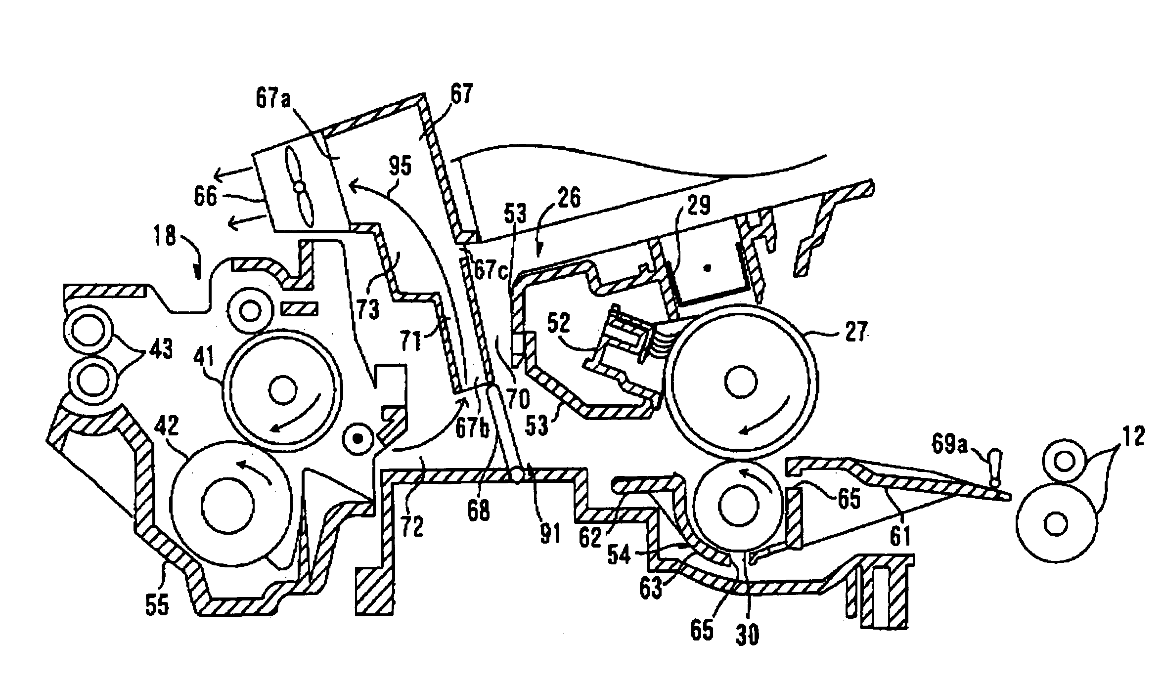
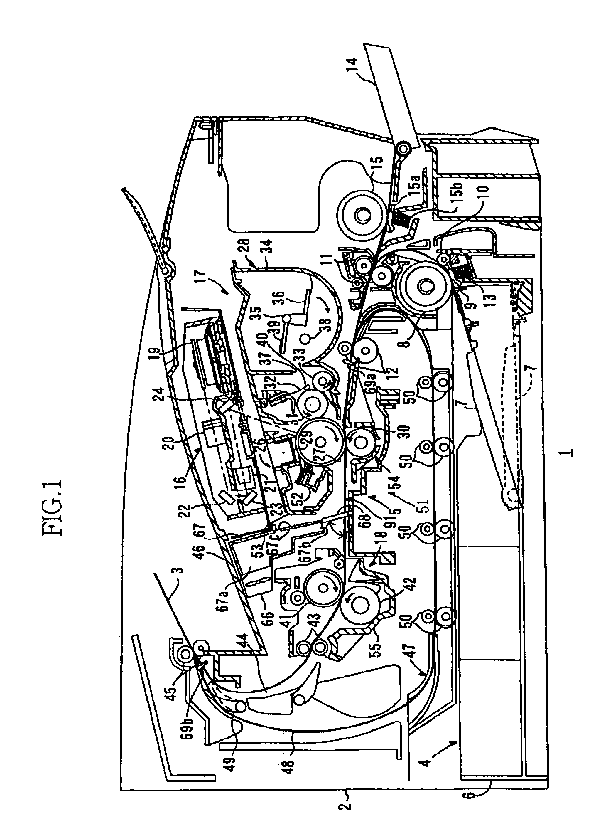
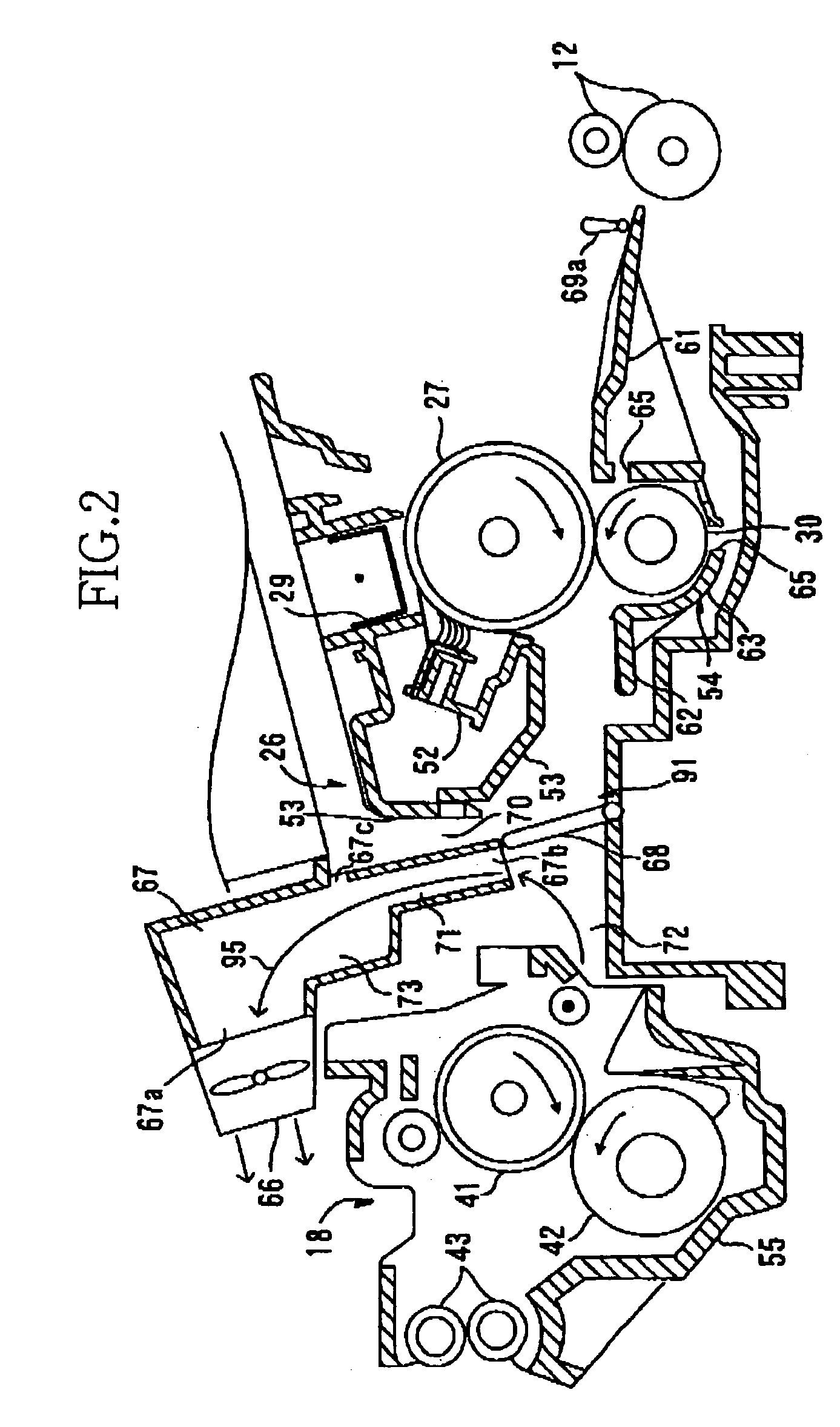
[0034] Hereinafter, there will be described a preferred embodiment of the present invention by reference to the drawings. FIG. 1 shows a laser printer 1 as an embodiment of an image forming apparatus in accordance with the present invention. In FIG. 1, the laser printer 1 includes a housing 2; a sheet feeding portion 4 that feeds recording sheets 3 each as a sort of recording medium that is a sort of transfer target or object; and an image forming portion 5 that forms an image on each recording sheet 3 fed from the sheet feeding portion 4. The sheet feeding portion 4 and the image forming portion 5 are provided in the housing 2.

[0035] The sheet feeding portion 4 includes a sheet feed tray 6; a sheet push plate 7; a sheet feed roller 8 and a sheet feed pad 9; sheet-dust removing rollers 10, 11; and register rollers 12. The sheet feed tray 6 is detachably attached to a bottom portion of the housing 2. The sheet push plate 7 is provided in the sheet feed tray 6. The feed roller and pa...


PUM


Abstract

A processing apparatus, including an image carrier which carries a developing-material image formed by developing an electrostatic latent image with a developing material, a transferring device which transfers the developing-material image from the image carrier to a transfer object, and a cover member which at least partly covers the transferring device. The cover member has one or more air-flow holes which allow an air to flow therethrough between an inner side thereof opposed to the transferring device and an outer side thereof opposite to the inner side.

Description

[0001] The present application is based on Japanese Patent Application P2003-352101, filed on Oct. 10, 2003, the contents of which are incorporated herein by reference. BACKGROUND OF THE INVENTION [0002] 1. Field of the Invention [0003] The present invention relates to an image forming apparatus such as a laser printer, and a processing apparatus which is employed by, e.g., an image forming apparatus. [0004] 2. Discussion of Related Art [0005] There has been known an image forming apparatus, such as a laser printer, that includes a photosensitive drum, and an electrifier, a scanner, a developing roller, and a transferring roller all of which are provided in the order of description around the photosensitive drum in the direction of rotation of the drum. As the photosensitive drum is rotated, first, an outer circumferential surface of the drum is uniformly electrified, i.e., electrically charged by the electrifier, and subsequently the outer surface is exposed to a high-speed scannin...

Claims


Application Information

Patent Timeline
Patent Type & Authority Applications(United States)
IPC IPC(8): G03G21/20G03G15/16
CPCG03G21/206G03G2221/1645
Inventor DEGUCHI, HIDEAKIISHIKAWA, SATORUHISADA, HIDENORI
Owner BROTHER KOGYO KK
Why Eureka
Try Eureka