Connector for electrical cords and cables

a technology for connecting cables and electrical cords, which is applied in the direction of connections, basic electric elements, electric devices, etc., can solve the problems of difficulty in connection, inability to keep an electrical cord or cable firmly in position, and inability to keep straight, so as to and improve the structure of the connector

Inactive Publication Date: 2005-04-14
HSIA YU CHAO
View PDF4 Cites 51 Cited by
  • Summary
  • Abstract
  • Description
  • Claims
  • Application Information

AI Technical Summary

Benefits of technology

[0013] It is the primary object of the present invention to provide an improvement in the structure of a connector, wherein the plastic engaging sleeve has a round tapered portion which serves to provide a compressing space in the manufacturing process. In the manufacturing process, the round tapered portion will be compressed, so that it will be flattened to have like a round cylinder.
[0014] Another object of the present invention is to provide an improvement in the structure of a connecotro which will not twist a cord or cable when engaged therewith.
[0015] It is another object of the present invention to provide an improvement in the structure of a connector which can firmly engaged with an electrical cord or cable.
[0016] It is a further object of the present invention to provide an improvement in the structure of a connector for electrical cords and cables which can prevent water from penetrate therein.

Problems solved by technology

As the conventional connector is connected with an electrical cord or cable, the electrical cord or cable will often be twisted, thereby making it unable to keep straight and therefore causing difficulty in connection.
The conventional electrical cord or cable simply uses a sleeve made of iron sheet to hold an electrical cord or cable, so that it cannot keep an electrical cord or cable firmly in position.
Furthermore, the procedures for the engagement between the cable and such a conventional connector are troublesome.
In addition, in the case of strong winds, the cable will disengage from the connector and water may also penetrate into the cable.
It is necessary to use pliers for the engagement of the cable and the conventional connector, but as the component fitted with a cable is made of plastic material so that it will be easily damaged or even broken when it is clamped by the pliers for engagement.
In brief, these patents do not use any means to protect the plastic component provided on the electric cable, so that the component will be easily damaged, deformed, or even broken when the component is engaged with the connector.
Furthermore, the cable cannot be firmly clipped and will easily disengage from the connector.
In addition, water will easily penetrate the cable.
These arrangement is unbeneficial in the manufacturing process since in the manufacturing process, the round portion will be clamped so that the round porition will deform.
Furthermore, the metal ring has no substantial effect of the connector.

Method used


Image

  • Connector for electrical cords and cables
  • Connector for electrical cords and cables
  • Connector for electrical cords and cables

Examples


Embodiment Construction

[0024] For the purpose of promoting an understanding of the principles of the invention, reference will now be made to the embodiment illustrated in the drawings. Specific language will be used to describe same. It will, nevertheless, be understood that no limitation of the scope of the invention is thereby intended, such alterations and further modifications in the illustrated device, and such further applications of the principles of the invention as illustrated herein being contemplated as would normally occur to one skilled in the art to which the invention relates.

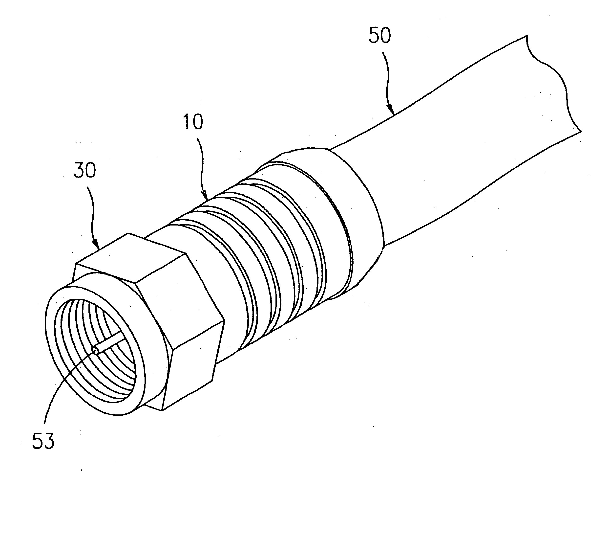
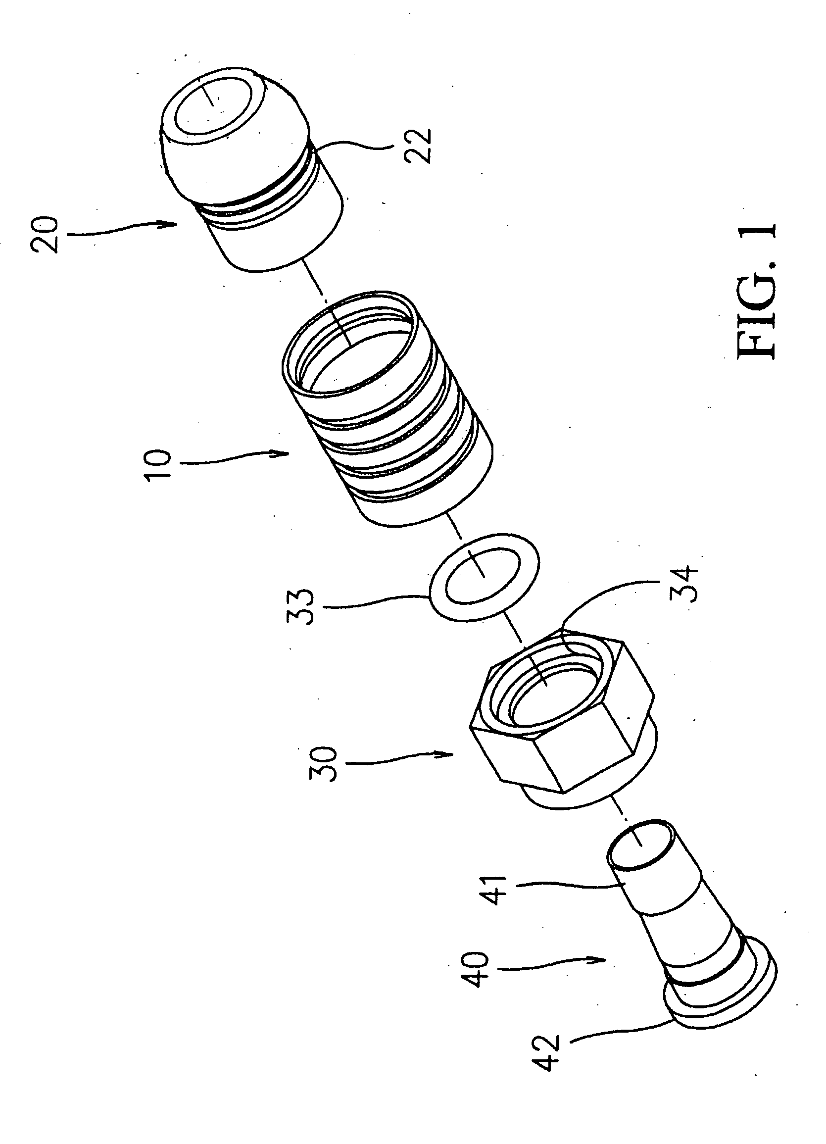
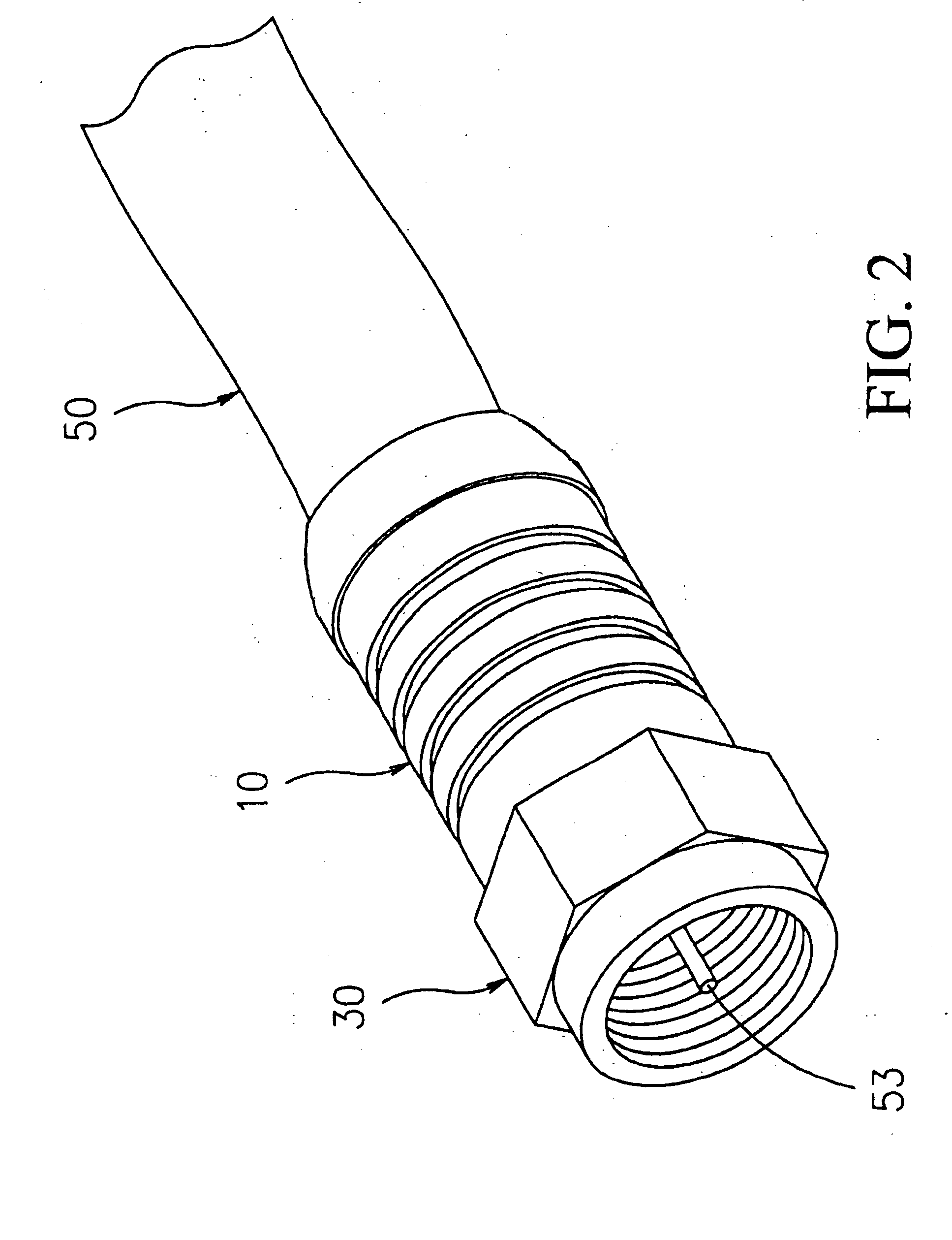
[0025] With reference to drawings and in particular to FIGS. 1 and 2 thereof, the connector for electrical cords and cables according to the present invention generally comprises a tubular body 10, a plastic engaging sleeve 20, a connecting sleeve 30, and a connecting plug 40.

[0026] Referring to FIGS. 1, 23 and 5, the tubular body 10 has a longitudinal through hole formed with a stepped recess 11 at the left end (wi...


PUM


Abstract

A connector for electrical cords and cables comprises a tubular body, a plastic engaging sleeve, a connecting sleeve and a connecting plug. The plastic engaging sleeve having a sleeve head; a circular groove behind to the sleeve head; a circular projection behind to the circular groove; a circular neck portion behind the circular projection; and a round tapered portion behind the circular neck portion; wherein the circular projection is configured to fit snugly into the circular groove of the tubular body; the round tapered portion serves to provide a compressing space in the manufacturing process. In the manufacturing process, the round tapered portion will be compressed, so that it will be flattened to have like a round cylinder.

Description

[0001] The invention is a continuation in part (CIP) of U.S. Pat. No. 6,241,553 assigned and invented by the inventor of the present invention. Therefore, the contents of U.S. Pat. No. 6,241,553 are incorporated into the present invention as a part of the present invention.BACKGROUND OF THE INVENTION [0002] 1. Field of the Invention [0003] This invention is related to an improvement in the structure of a connector for electrical cords and cables. [0004] 2. Description of the Prior Art [0005] As the conventional connector is connected with an electrical cord or cable, the electrical cord or cable will often be twisted, thereby making it unable to keep straight and therefore causing difficulty in connection. [0006] The conventional electrical cord or cable simply uses a sleeve made of iron sheet to hold an electrical cord or cable, so that it cannot keep an electrical cord or cable firmly in position. Furthermore, the procedures for the engagement between the cable and such a conventi...

Claims


Application Information

Patent Timeline
Patent Type & Authority Applications(United States)
IPC IPC(8): H01R9/05
CPCH01R9/0521
Inventor HSIA, YU-CHAO
Owner HSIA YU CHAO
Why Eureka
Try Eureka