Golf ball with improved flight performance

a golf ball and flight performance technology, applied in the field of golf balls, can solve the problems of not having a teaching in the art for a golf ball that is optimal for all ball speeds, most of these factors are outside the control of a golfer, etc., and achieve the effect of improving aerodynamic efficiency and increasing flight distance for golfers

Inactive Publication Date: 2005-04-14
ACUSHNET CO
View PDF37 Cites 73 Cited by
  • Summary
  • Abstract
  • Description
  • Claims
  • Application Information

AI Technical Summary

Benefits of technology

The present invention is directed to golf balls having improved aerodynamic efficiency, resulting in increased flight distance for golfers of all swing speeds, and more particularly for golfers possessing very high swing speeds, such as those who can launch the balls at an initial speed greater than 160 miles per hour and more particularly at initial ball speed of about 170 miles per hour or higher.

Problems solved by technology

The flight of a golf ball is determined by many factors; however, most of these factors are outside of the control of a golfer.
However, there is no teaching in the art for a golf ball that is optimal for all ball speeds, including the very high ball speeds generated by today's players.

Method used


Image

  • Golf ball with improved flight performance
  • Golf ball with improved flight performance
  • Golf ball with improved flight performance

Examples


first embodiment

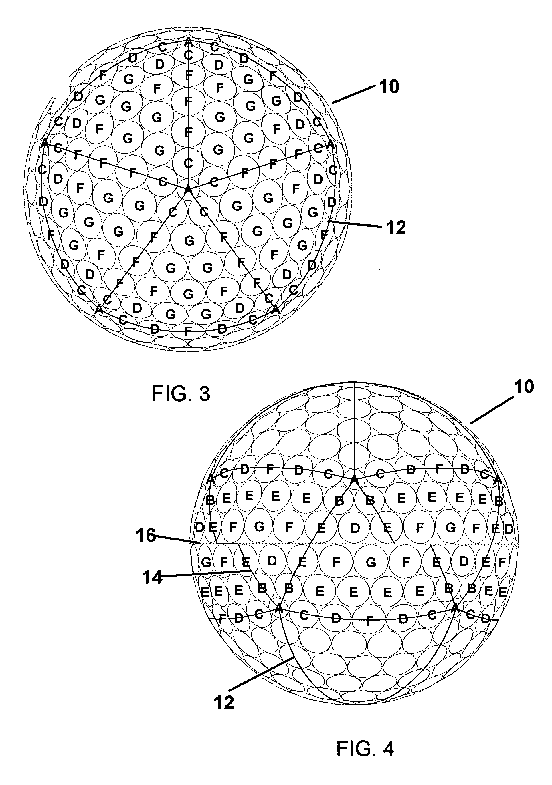
As shown in FIG. 3 and in accordance to the present invention, a golf ball 10 comprises a plurality of dimples arranged in an icosahedron pattern. Generally, an icosahedron pattern comprises twenty triangles with five triangles sharing a common vertex coinciding with each pole, and ten triangles disposed between the two five-triangle polar regions. Other suitable dimple patterns include dodecahedron, octahedron, hexahedron and tetrahedron, among others. The dimple pattern may also be defined at least partially by phyllotaxis-based patterns, such as those described in U.S. Pat. No. 6,338,684.

The first embodiment comprises seven different sized dimples, as shown in Table 1 below:

TABLE 1Dimples and Dimple Pattern of the First EmbodimentNumber ofSurfaceDimpleDiameter (inch)DimplesCoverage %A0.115121.4B0.155204.3C0.160409.1D0.1655012.1E0.1706015.4F0.1758021.8G0.1807020.1Total33284.2%

These dimples form twenty triangles 12, with the smallest dimples A occupying the vertices and the lar...

second embodiment

Similarly, ball 20 can be modified to include an equator or parting line on its surface. The icosahedron pattern is modified around the midsection to create a great circle that does not intersect any dimple. The dimple arrangement shown in FIG. 5 then illustrates the polar regions of this modification, and the dimple arrangement shown in FIG. 6 illustrates the equatorial region. The dimple population and surface coverage shown in Table 2 illustrate the dimple arrangement of the modified second embodiment shown in FIGS. 5 and 6. This embodiment comprises only 252 dimples having six different sizes.

As shown in FIG. 6, ball 20 comprises ten modified triangles 24 disposed around parting line or equator 26. As shown, each triangle 24 is defined to have smallest dimples A at the vertices, and unlike triangles 14 each triangle 24 does not have an irregular side. The sizes and positions of the dimples are adjusted so that parting line 26 may pass through triangles 24 without intersecting a...


PUM


Abstract

A golf ball is provided that has improved aerodynamic efficiency, resulting in increased flight distance for golfers of all swing speeds, and more particularly for golfers possessing very high swing speeds, such as those who can launch the balls at an initial speed greater than 160 miles per hour and more particularly at initial ball speed of about 170 miles per hour or higher. The golf ball of the present invention combines lower dimple count with multiple dimple sizes to provide higher dimple coverage and improved aerodynamic characteristics.

Description

FIELD OF THE INVENTION The present invention relates to golf balls having improved aerodynamic characteristics that yield improved flight performance and longer ball flight. BACKGROUND OF THE INVENTION The flight of a golf ball is determined by many factors; however, most of these factors are outside of the control of a golfer. While a golfer can control the speed, the launch angle, and the spin rate of a golf ball by hitting the ball with a particular club, the distance that the ball travels after impact depends upon ball aerodynamics, construction and materials, as well as environmental conditions, e.g., terrain and weather. Since flight distance and consistency are critical factors in reducing golf scores, manufacturers continually strive to make improvements in golf ball flight consistency and flight distance through improving various aerodynamic properties and golf ball constructions. Before the 1970s, most golf balls had 336 dimples arranged in an octahedron pattern, and ha...

Claims


Application Information

Patent Timeline
Patent Type & Authority Applications(United States)
IPC IPC(8): A63B37/00A63B37/04
CPCA63B37/0004A63B37/0077A63B37/0017A63B37/0018A63B37/0021A63B37/0064A63B37/0076A63B37/0078A63B2037/0079A63B37/0012A63B37/0019A63B37/002A63B37/003A63B37/0045A63B37/0087A63B37/0089A63B37/009A63B37/0096A63B37/0006A63B37/00776A63B37/00215
Inventor AOYAMA, STEVENJONES, DOUGLAS E.
Owner ACUSHNET CO
Why Eureka
Try Eureka