
Intervertebral implant

a technology of intervertebral implants and implants, applied in the field of intervertebral implants, can solve the problem of completely missing the joint, and achieve the effect of high abrasion resistan

Inactive Publication Date: 2005-04-14
AESCULAP AG
View PDF51 Cites 158 Cited by
  • Summary
  • Abstract
  • Description
  • Claims
  • Application Information

AI Technical Summary

Benefits of technology

[0008] For example, the displaceably mounted bearing part known from FR 2 730 159 can be effectively prevented, with the restoring device of the present invention, from being able to strike lateral edges of the anchoring part and being damaged as a result. Undesired abrasion is thus avoided and the life of the implant as a whole is prolonged. Moreover, the design supports the maintenance of the intervertebral implant in its normal position. The restoring device of the present invention promotes the stability of the intervertebral disk, especially in patients who have weakened muscles. On the whole, the natural mobility is reconstructed nearly optimally with the intervertebral implant according to the present invention because, just as in the natural intervertebral disk, a translational motion of a joint center in parallel to the plane of motion is damped.
[0040] It is favorable if the physiologically compatible material is a metal, a ceramic or a plastic. The materials, in particular, metal or plastic, can be processed in a simple manner, and, moreover, ceramic has a high abrasion resistance, which is especially well suited for forming surfaces of joint parts or joint parts as a whole.

Problems solved by technology

The drawback of the prior-art intervertebral disk prostheses with at least one joint part mounted movably in relation to the corresponding anchoring part is that the joint part is completely freely movable and may strike the edges of a recess in the anchoring part and may be damaged as a result.

Method used


Image

  • Intervertebral implant
  • Intervertebral implant
  • Intervertebral implant

Examples


Embodiment Construction

[0052] Although the invention is illustrated and described herein with reference to specific embodiments, the invention is not intended to be limited to the details shown. Rather, various modifications may be made in the details within the scope and range of equivalents of the claims and without departing from the invention.

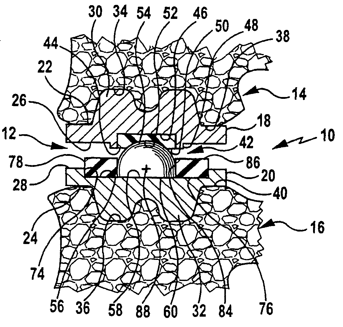
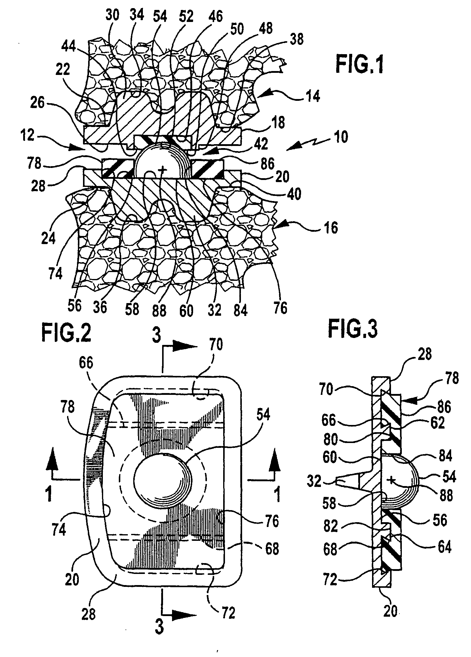
[0053]FIG. 1 shows an intervertebral disk prosthesis designated as a whole by the reference number 10. It is inserted in an intervertebral space 12 between a first vertebral body 14 and a second vertebral body 16.

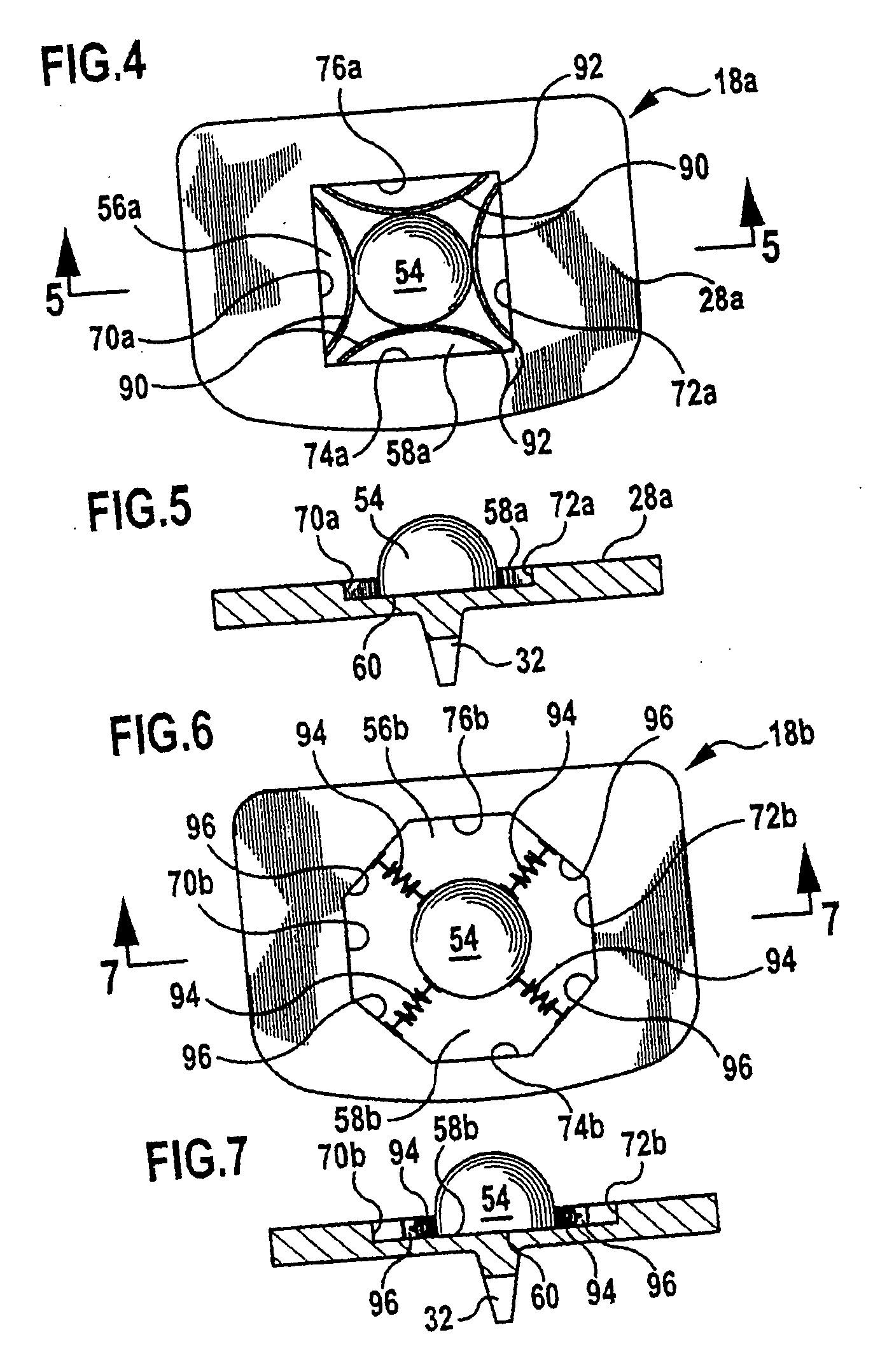
[0054] The intervertebral disk prosthesis 10 as a whole has an essentially two-part design and comprises a first base plate 18 and a second base plate 20, which comprise a respective anchoring surface 22 and 24 each and a respective bearing surface 26 and 28 each. Narrow, plate-like anchoring ribs 30 and 32, which are driven into the vertebral bodies 14 and 16 to anchor the base plates 18 and 20 or are inserted into respective recesses 34 and 36 prepar...


PUM


Abstract

An intervertebral implant is provided for insertion between a first vertebral body and a second vertebral body defining an intervertebral space. The implant includes a first anchoring part for anchoring at the first vertebral body, a second anchoring part for anchoring at the second vertebral body, and a joint configured to connect the first and second anchoring parts together. The joint includes a first joint part carried by the first anchoring part, and a second joint part carried by the second anchoring part. The implant further includes at least one restoring device adapted to exert a restoring force on the first or second joint part. The restoring force of the at least one restoring device transfers the first or second joint part from a deflected position back to a normal position and / or limits movement of the first or second joint part away from the normal position.

Description

[0001] This application is related to and claims the benefit of German Utility Model No. 203 15 611.0 entitled Intervertebral Implant issued on Dec. 11, 2003, and German Patent Application No. 103 47 172.3 filed Oct. 8, 2003. FIELD OF THE INVENTION [0002] The present invention pertains to an intervertebral implant with which the original height of the intervertebral disk can be restored in case of, e.g., degeneratively altered intervertebral disks, and the function can be preserved at the same time. BACKGROUND OF THE INVENTION [0003] Intervertebral implants are used, among other things, in the case of degeneratively altered intervertebral disks as the replacement thereof in order to restore an original intervertebral disk height while preserving the function at the same time. Numerous embodiments of intervertebral implants in the form of intervertebral disk prostheses are known, and most of the prostheses used clinically are based on the principle of the ball and socket joint, in wh...

Claims


Application Information

Patent Timeline
Patent Type & Authority Applications(United States)
IPC IPC(8): A61F2/00A61F2/30A61F2/44
CPCA61F2/30767A61F2310/00179A61F2002/30369A61F2002/30388A61F2002/30563A61F2002/30568A61F2002/30571A61F2002/30649A61F2002/30685A61F2002/30733A61F2002/30884A61F2002/443A61F2220/0025A61F2220/0033A61F2310/00011A61F2/4425A61F2002/30387
Inventor SCHULTZ, ROBERT
Owner AESCULAP AG
Learn More