Adjustable spanner

Inactive Publication Date: 2005-04-21
HSIEN CHIH CHING
View PDF10 Cites 7 Cited by
  • Summary
  • Abstract
  • Description
  • Claims
  • Application Information

AI Technical Summary

Benefits of technology

[0006] The primary objective of the present invention is to provide

Problems solved by technology

Thus, the user's hand touches and rubs the surface of the workpiece successively, thereby greatly causing inconvenience to the user during operation.
In addition, the conventional adjustable spann

Method used


Image

  • Adjustable spanner
  • Adjustable spanner
  • Adjustable spanner

Examples


Embodiment Construction

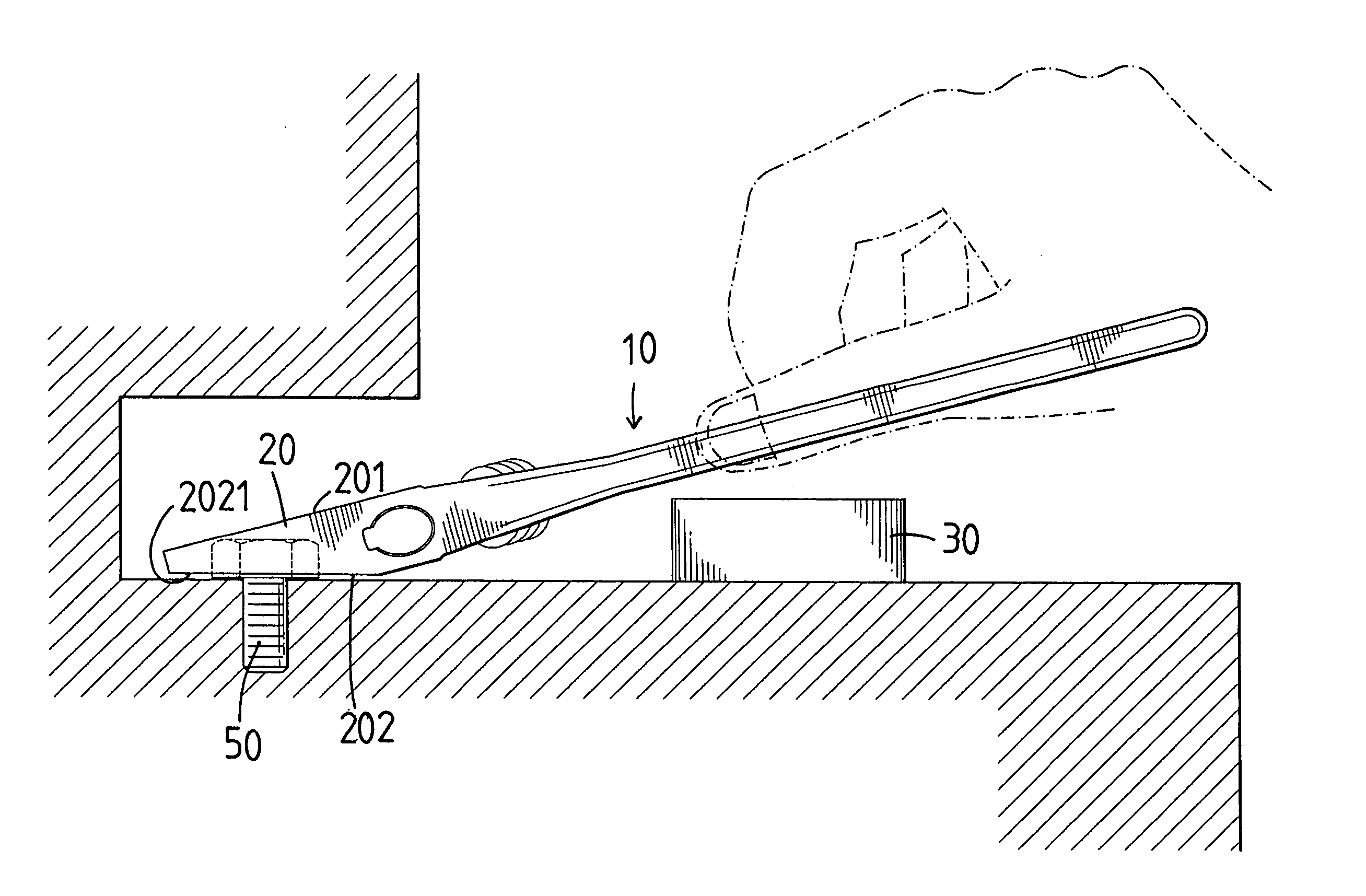
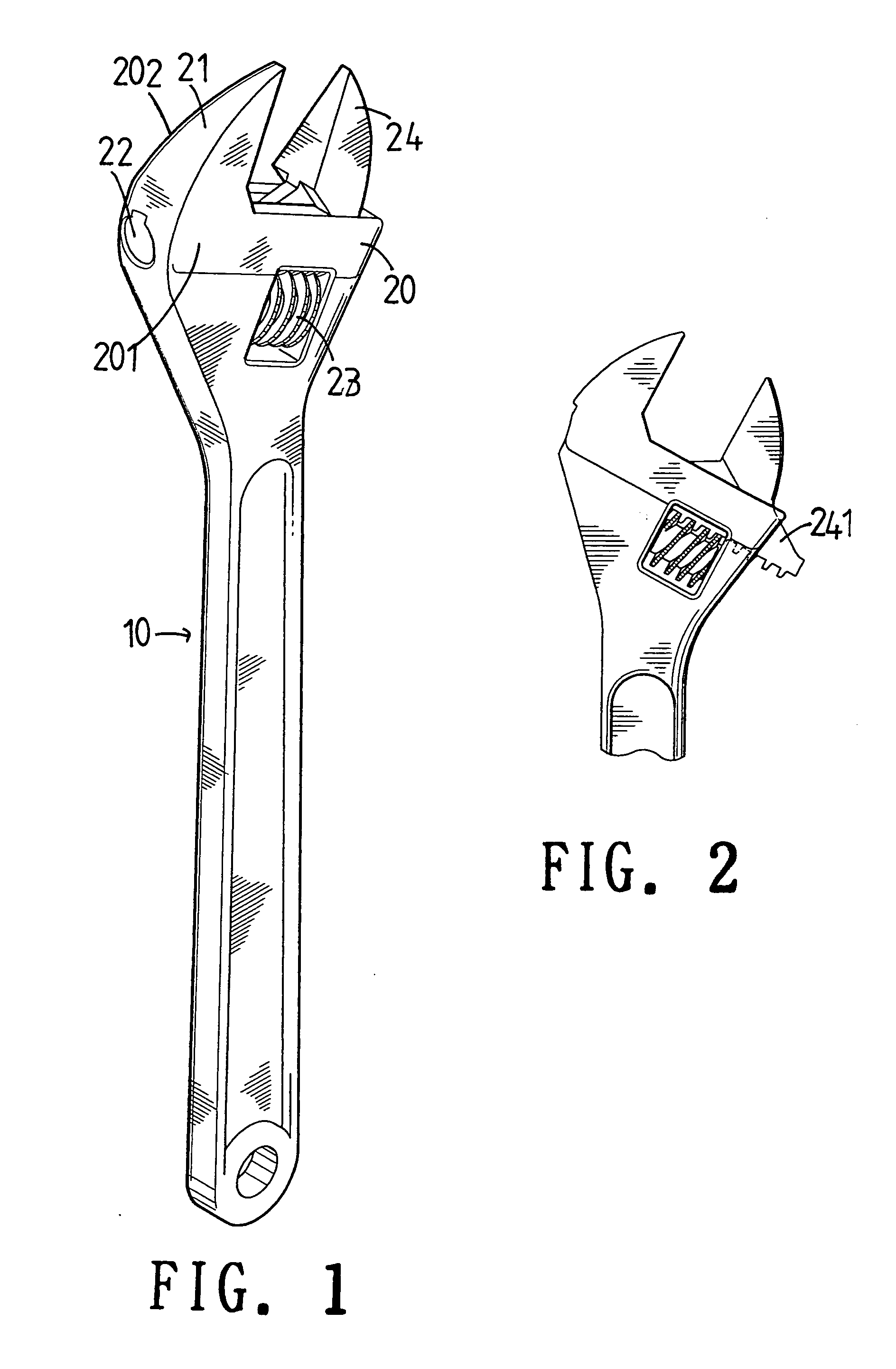
[0022] Referring to the drawings and initially to FIGS. 1-4, an adjustable spanner in accordance with the preferred embodiment of the present invention comprises a main body 10 having an end formed with a drive portion 20 formed with a fixed jaw 21 and a slideway 22, an adjustment screw 23 rotatably mounted in the main body 10, and a movable jaw 24 movably mounted on the drive portion 20 and having a bottom formed with a rack 241 slidably mounted in the slideway 22 of the drive portion 20 and engaged with the adjustment screw 23. Thus, the rack 241 is moved by rotation of the adjustment screw 23, so that the movable jaw 24 is moved relative to the fixed jaw 21.

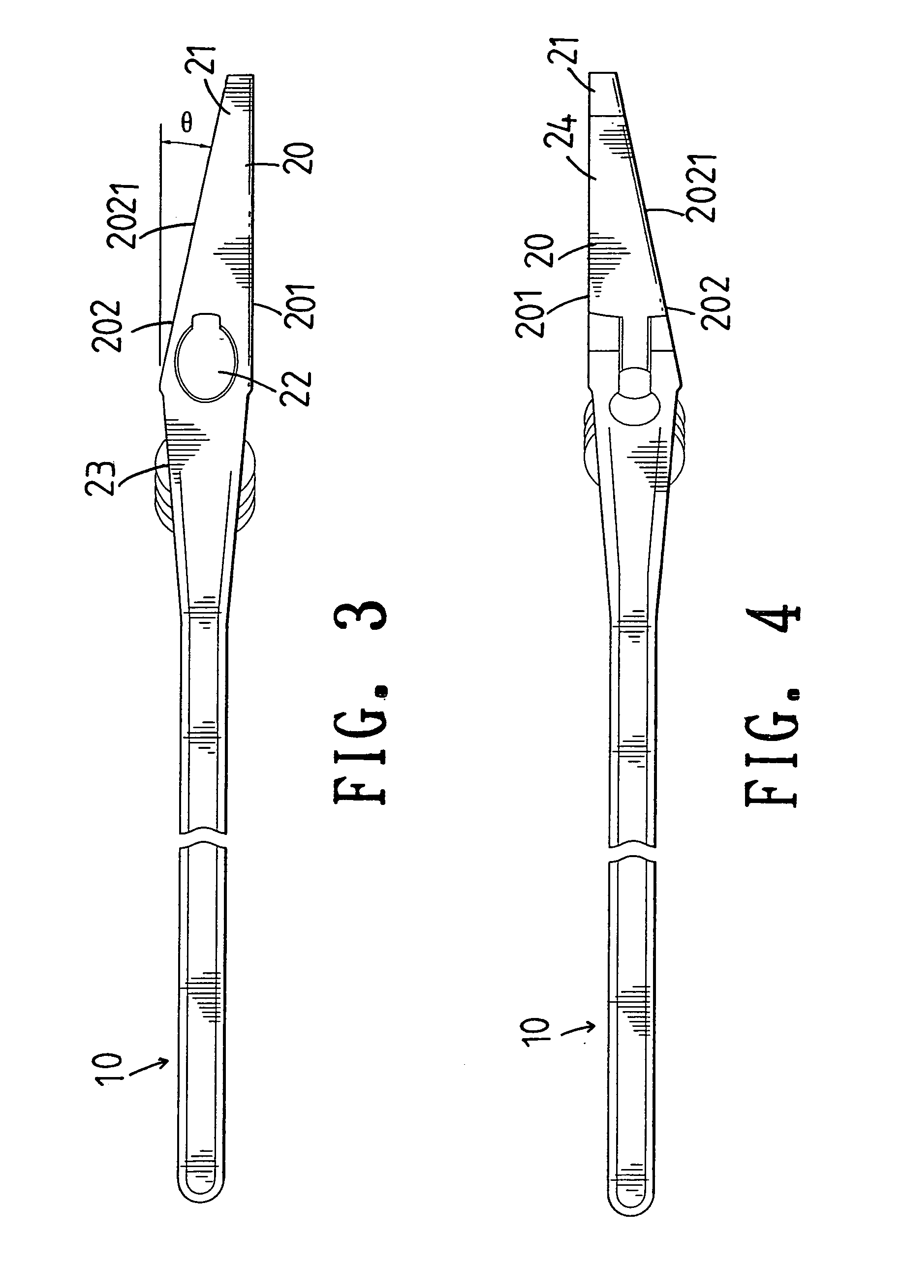
[0023] The drive portion 20 has a first side 201 and a second side 202. The first side 201 of the drive portion 20 is in parallel with the main body 10. The second side 202 of the drive portion 20 is formed with an inclined face 2021 inclined toward the first side 201 of the drive portion 20, so that an included angle θ is de...


PUM


Abstract

An adjustable spanner includes a main body having an end formed with a drive portion having a first side and a second side. The second side of the drive portion is formed with an inclined face inclined toward the first side of the drive portion. Thus, the adjustable spanner is provided with an inclined face, so that the adjustable spanner can be used to operate a screw member located adjacent to an obstruction or located at a deeper zone of a workpiece, thereby facilitating the user operating the adjustable spanner.

Description

BACKGROUND OF THE INVENTION [0001] 1. Field of the Invention [0002] The present invention relates to an adjustable spanner, and more particularly to an adjustable spanner that can be operated conveniently. [0003] 2. Description of the Related Art [0004] A conventional adjustable spanner comprises a main body having a first end formed with a drive portion and a second end formed with a handle portion. Thus, the user's one hand can hold the handle portion to rotate the drive portion so as to rotate a screw member on a workpiece. [0005] However, the handle portion and the drive portion are located at the same plane, so that when the drive portion is rested on the screw member, the handle portion is also rested on the surface of the workpiece. Thus, the user's hand touches and rubs the surface of the workpiece successively, thereby greatly causing inconvenience to the user during operation. In addition, the conventional adjustable spanner cannot be used to operate a screw member located...

Claims


Application Information

Patent Timeline
IPC IPC(8): B25B13/14B25B13/48
CPCB25B13/481B25B13/14
Inventor HSIEN, CHIH-CHING
Owner HSIEN CHIH CHING
Why Eureka
Try Eureka