Aircraft defueling apparatus and method

a technology for aircraft and defueling, applied in the field of aircraft equipment, can solve the problems of presenting a great obstacle to safe defueling, and achieve the effect of safe and convenient defueling and safe defueling

Active Publication Date: 2005-04-21
SPOKANE STAINLESS TECH INC
View PDF4 Cites 15 Cited by
  • Summary
  • Abstract
  • Description
  • Claims
  • Application Information

AI Technical Summary

Benefits of technology

[0006] The defueling fitting facilitates safe and convenient defueling of certain aircraft that have unique configurations, such as recessed or covered fuel drain valves. For example, the Boeing C-17 has fuel drain valves that are recessed behind doors, heretofore presenting a great obstacle to safely defueling. The defueling fitting described herein may be used in small and tight spaces, even when other conventional defueling fittings are not helpful.

Problems solved by technology

For example, the Boeing C-17 has fuel drain valves that are recessed behind doors, heretofore presenting a great obstacle to safely defueling.

Method used


Image

  • Aircraft defueling apparatus and method
  • Aircraft defueling apparatus and method
  • Aircraft defueling apparatus and method

Examples


Embodiment Construction

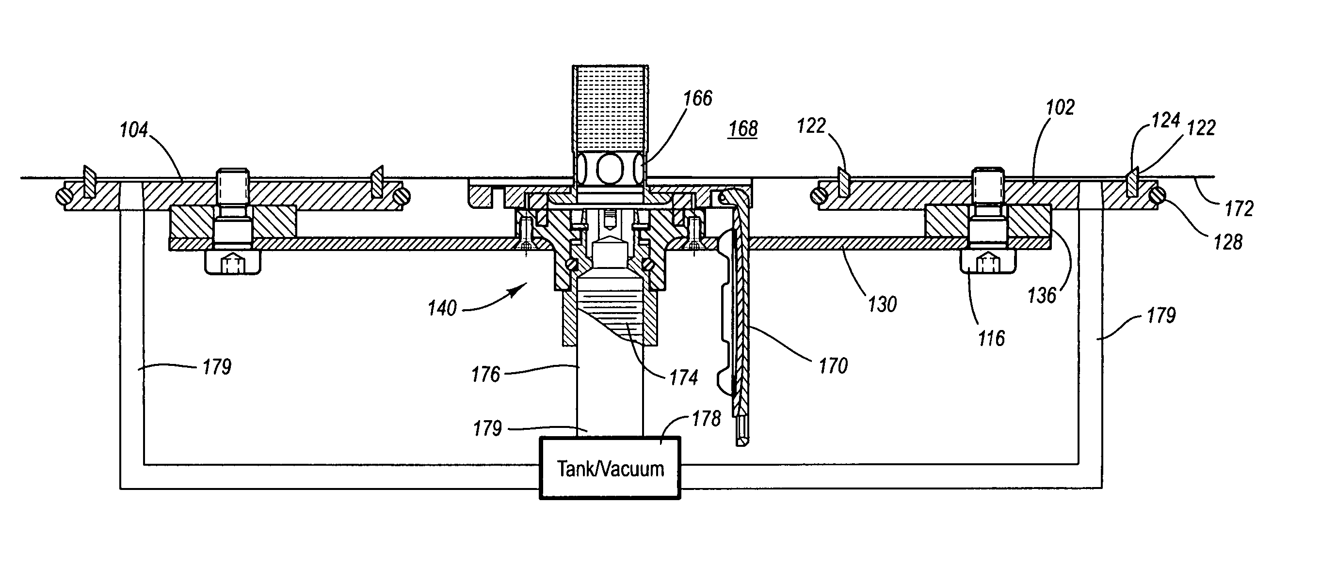
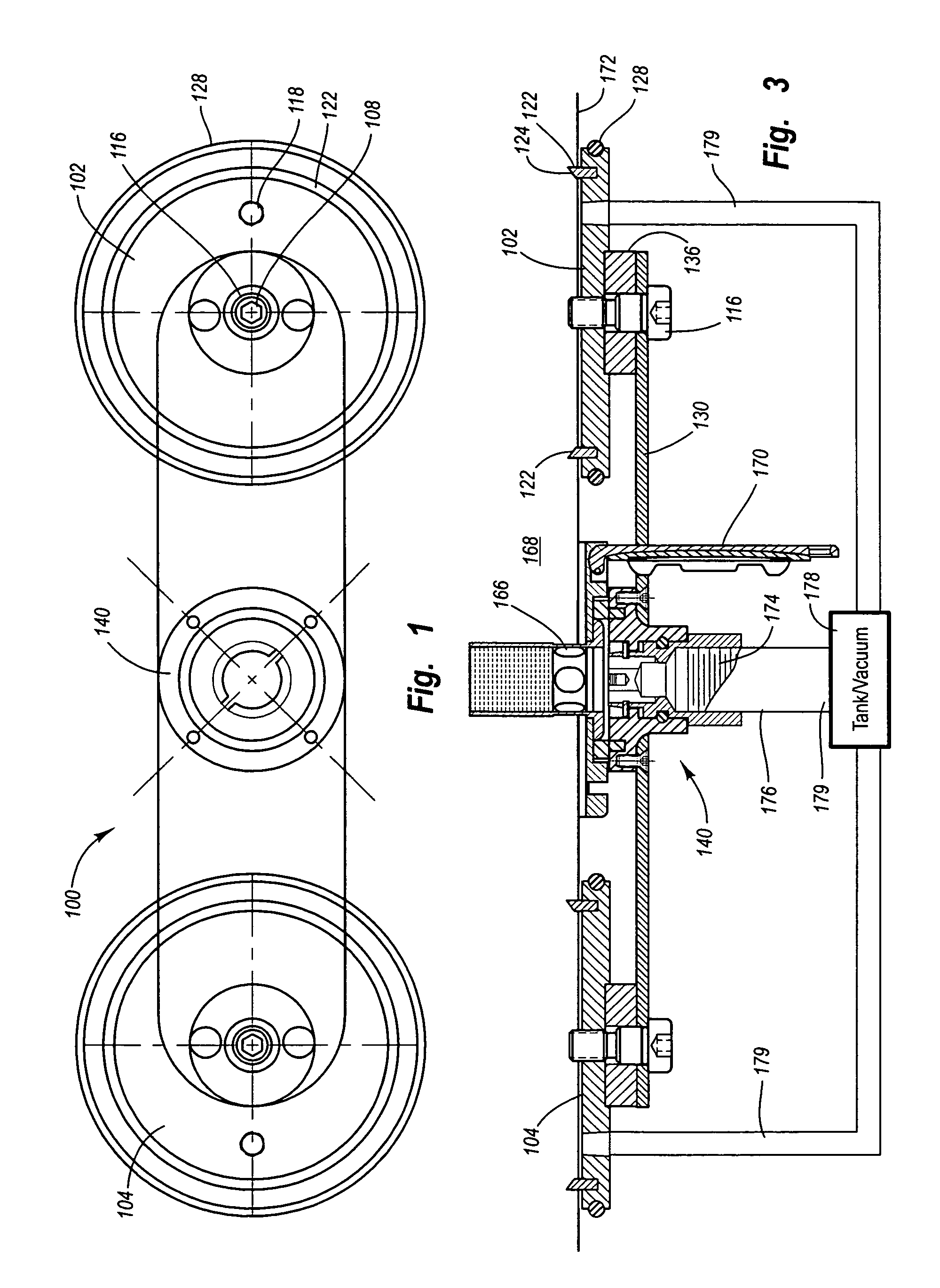
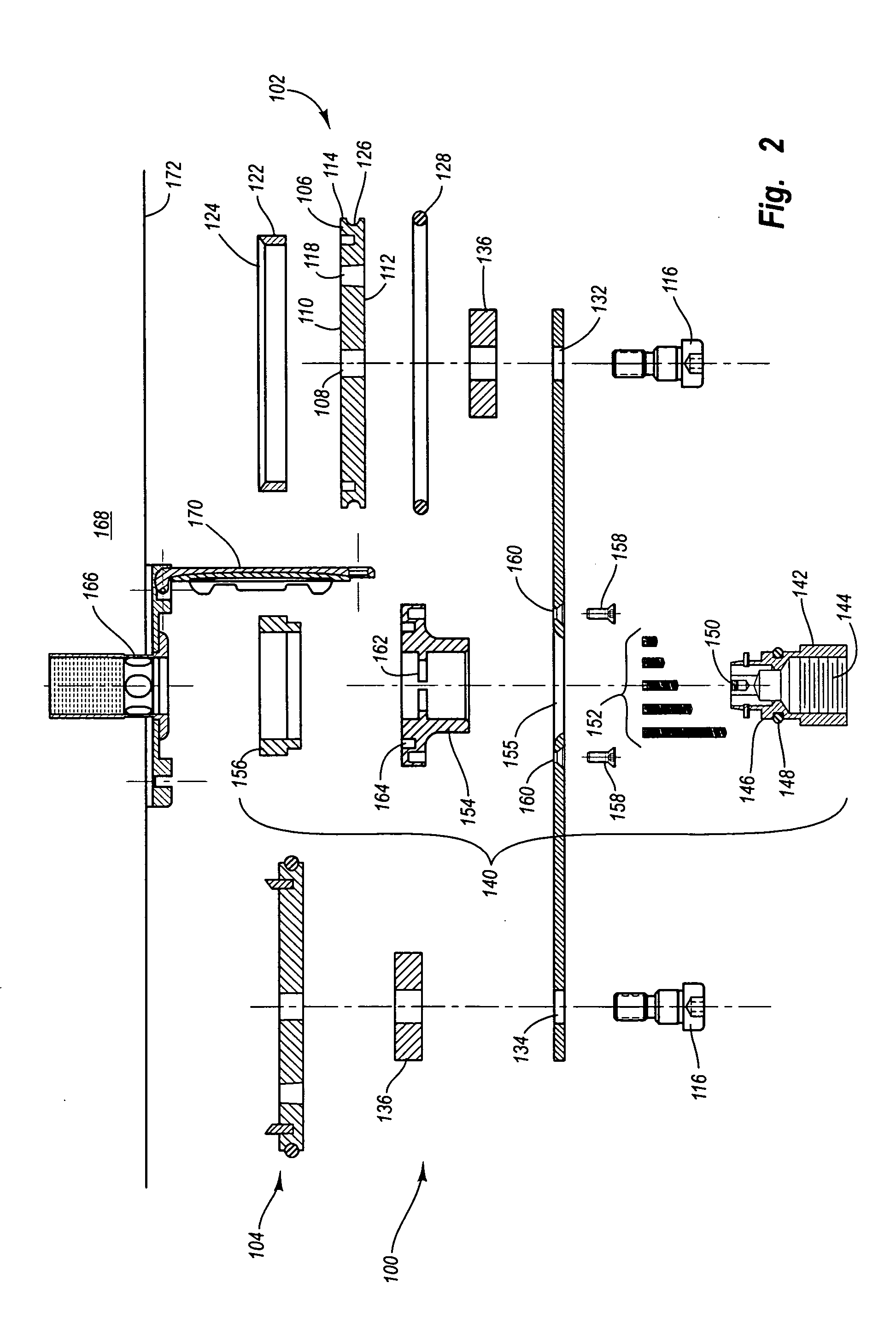
[0015] It is a very common procedure to defuel an aircraft prior to maintenance or repair. Most aircraft include one or more drain valves at low points of the fuel tanks to facilitate defueling. The drain valves are usually spring loaded “poppet” valves that are opened by the application of a force normal to the spring force. The drain valves of most aircraft are flush with the outside body of the aircraft and therefore readily accessible with few or no local obstructions. However, some aircraft include recessed fuel drain valves that are more difficult to access. Some recessed fuel drain valves are located adjacent or behind structures, such as doors, that are generally flush with the outside body of the aircraft. Such structures must sometimes be opened to gain access to the drain valve. For example, the Boeing C-17 is equipped with recessed fuel drain valves normally housed behind closed doors. Other fuel drain valves are placed in small or difficult-to-access locations that comp...


PUM

PropertyMeasurementUnit
vacuumaaaaaaaaaa
lengthaaaaaaaaaa
suctionaaaaaaaaaa

Abstract

A method and apparatus for defueling an aircraft. The apparatus includes a defueling fitting comprising one or more structural connectors, which may include one or more suction cups. The one or more structural members are attached to a mount. The mount may be of any shape, including generally straight, angled, polygonal, or circular. An actuator assembly is attached to the mount for opening an aircraft defueling valve. The first and second suction cups are operatively connected to a vacuum source to connect the defueling fitting to an aircraft body, with the actuator assembly positioned at the aircraft defueling valve. The defueling fitting facilitates safe and convenient defueling of certain aircraft that have recessed or covered fuel drain valves. For example, the Boeing C-17 has fuel drain valves that are recessed behind doors, heretofore presenting a great obstacle to appropriate defueling. The defueling fitting described herein may be used in small and tight spaces, even when other conventional defueling fittings are not helpful.

Description

FIELD OF THE INVENTION [0001] The present invention relates to aircraft equipment, and more particularly to a method and apparatus for defueling an aircraft. BACKGROUND OF THE INVENTION [0002] Generally, aircraft often need to be defueled prior to performing certain types of maintenance or repairs. There are generally three stages of aircraft defueling: pumping (removing the majority of fuel from the aircraft fuel cells), bottom sumping (removing most of the remaining fuel from the bottom of the fuel cells—traditionally done by some type of gravity feed), and depuddling (which involves removing the small puddles remaining in the fuel cells). A number of aircraft defueling systems have traditionally been available to handle the various stages of aircraft defueling. At some point, however, most defueling systems require some type of gravity feed, resulting in low drain rates and long drain times. In fact, for many large aircraft, depending on the amount of fuel remaining in the tanks,...

Claims


Application Information

Patent Timeline
Patent Type & Authority Applications(United States)
IPC IPC(8): B64D37/20B64F1/28
CPCB64F1/28B64D37/20
Inventor KUNTZ, JAMES P.
Owner SPOKANE STAINLESS TECH INC
Why Eureka
Try Eureka