Plasma display panel with improved data structure

a plasma display panel and data structure technology, applied in the field of data structure, can solve the problems of ineffective utilization of discharge areas and obvious disadvantages of conventional reflective pdp

Inactive Publication Date: 2005-04-21
AU OPTRONICS CORP
View PDF6 Cites 2 Cited by
  • Summary
  • Abstract
  • Description
  • Claims
  • Application Information

AI Technical Summary

Benefits of technology

[0009] Accordingly, the present invention has been made in consideration of the above disadvantages in the conventional reflective PDPs. One example of the present invention provides a plasma display panel with a triangular sub-pixel arrangement and a closed barrier rib structure defining a plurality of cell areas. Particularly, the panel includes sustain and data electrodes, wherein each sustain electrode is spaced apart in a row ...

Problems solved by technology

The disadvantages of a conventional reflective PDP are evident in view of an stripe barrier rib construction as sho...

Method used


Image

  • Plasma display panel with improved data structure
  • Plasma display panel with improved data structure
  • Plasma display panel with improved data structure

Examples


Embodiment Construction

[0021] Reference will now be made in detail to the exemplary embodiment of the present invention, examples of which are illustrated in the accompanying drawings.

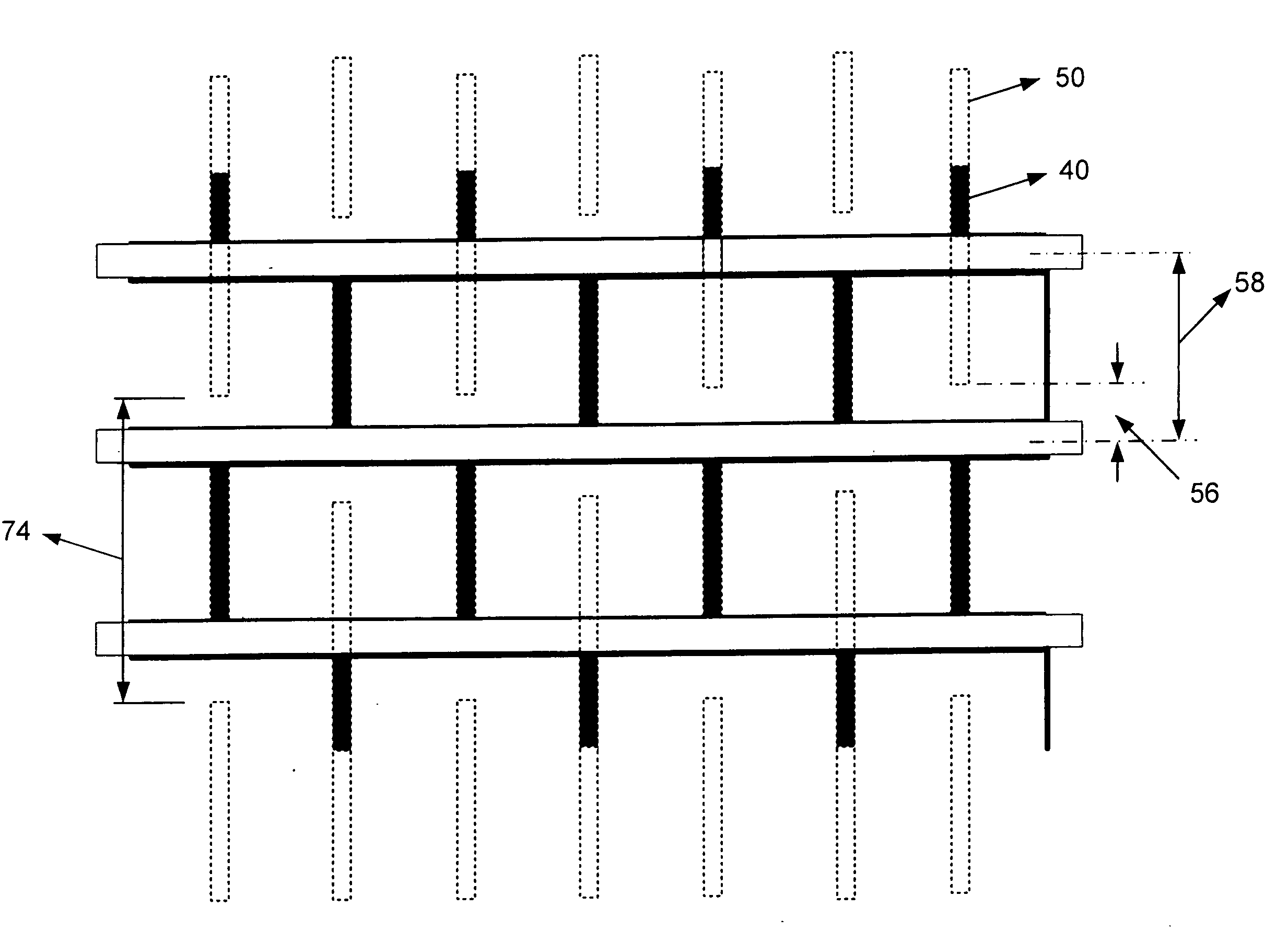
[0022] The present invention is directed to a plasma display panel which is constructed using a closed barrier rib structure and a triangular sub-pixel arrangement. As shown in FIGS. 4a and 4b, barrier ribs 40 can be divided into column barrier ribs 42 and row barrier ribs 44 and partitioned in a polygon or rectangular manner to define a plurality of sub-pixel cells 46 with red, green, and blue (RGB) phosphor layers disposed therein. Particularly, each sub-pixel cell 46 has a cell area which is defined by the column barrier ribs 42 intersecting the row barrier ribs 44. An RGB color pixel is formed by a group of red, green and blue sub-pixel cells 46 in a delta configuration. The combination of the RGB sub-pixel cells for each adjacent color pixels can be reversed in a sequential order. The closed barrier rib structure elimi...


PUM


Abstract

The present invention relates to a plasma display panel with barrier ribs configured in a closed shape. The panel has sub-pixel cells each with a cell area that is defined by the closed shape barrier ribs, sustain electrodes each spaced apart in a row direction at a predetermined cell length, and data electrodes each overlapping a barrier rib wall in a column direction and extending under the cell area. A plurality of the sub-pixels cells in a delta configuration defines a color pixel, whereby a dual scan gap of a predetermined gap length is formed between a pair of the data electrodes in the column direction, and a gap is formed between the row barrier ribs and data electrodes.

Description

BACKGROUND OF THE INVENTION [0001] 1. Field of the Invention [0002] The present invention generally relates to improvements in a plasma display panel, and more particularly to an improved data structure in the plasma display panel forming a large luminance region. According the invention that data structure will to prevent discharge errors around dual scan gap area, that said dual scan gap area is interface area of between first and second group data electrode. [0003] 2. Related Art [0004] Plasma display panels (PDPs) have become increasingly popular in the electronic industry. FIGS. 1a and 1b show a typical reflective type PDP. The PDP in FIG. 1a includes first and second substrates 10a and 10b in parallel, there are sequentially provided a plurality of sustain electrode pairs (scan, common electrode). The sustain electrode consisted of a transparent electrodes 12 is disposed on the first substrate 10a and extending along a row direction, and a bus electrodes 14 is disposed on the ...

Claims


Application Information

Patent Timeline
IPC IPC(8): G09G3/28H01J9/02H01J11/02H01J17/04H01J17/16
CPCH01J11/12H01J11/26H01J2211/365H01J2211/265H01J2211/326H01J11/32
Inventor SU, YAO-CHINGSUNG, WEN-FA
Owner AU OPTRONICS CORP
Why Eureka
Try Eureka