Video camera apparatus

a technology of video camera and video frame, which is applied in the field of video camera equipment, can solve the problems of subject which has so far been recognized, subject which is lost sight, and the accuracy of an af operation degrades, and achieves the effect of stable automatic focus adjustmen

Inactive Publication Date: 2005-04-21
CANON KK
View PDF5 Cites 14 Cited by
  • Summary
  • Abstract
  • Description
  • Claims
  • Application Information

AI Technical Summary

Benefits of technology

[0016] A first object of the present invention which has been made to solve the above-described problem is to provide a video camera capable of effecting stable automatic focus adjustment even during zooming.
[0017] A second object of the present invention is to provide a video camera capable of effecting stable automatic focus adjustment irrespective of a variation of a subject image due to zooming, as well as capable of effecting a natural and smooth operation.
[0019] A third object of the present invention is to provide a video camera having electronic-zoom means for electronically enlarging and reducing an image, which is capable of performing a stable and accurate automatic focus adjusting operation irrespective of an image variation due to an electronic-zoom operation.
[0021] In accordance with the above-described arrangement, in a case where zooming toward a telephoto end is performed with a variator lens positioned in the vicinity of the telephoto end, if AF control executed immediately before the zooming uses a large distance measuring frame, the zooming is performed with the large distance measuring frame active. Accordingly, it is possible to prevent a subject from being lost sight of during switching between the distance measuring frames. Further, since it is possible to prevent the phenomenon in which a subject suddenly disappears from the picture while the angle of view is varying, it is possible to realize stable zooming performance while maintaining stable focusing performance.
[0023] Particularly while the electronic zoom is in operation (while the image magnification is varying), if the enlargement of the image is started with an AF control frame (or distance measuring frame) large, AF control is performed with the large distance measuring frame active, until the image magnification reaches a particular magnification. When the electronic zoom is stopped (the image is fixed at a particular image magnification), the size of the distance measuring frame is set according to the image magnification. Accordingly, it is possible to realize a stable AF operation which causes no unnatural defocusing during AF control while an image is being enlarged.
[0024] Another object of the present invention is to provide a video camera provided with optical-zoom means and electronic-zoom means and capable of causing both of the optical- and electronic-zoom means to smoothly perform their respective zooming operations, and further capable of stably performing an automatic focus adjusting operation free of malfunction in either of the zooming operations.

Problems solved by technology

However, if the distance measuring frame is fixed in the central portion of the picture, the following problem will be experienced.
If a subject which is being photographed moves out of the distance measuring frame, it is determined that the subject has disappeared, and the focusing lens is made to move in a direction in which defocusing occurs, from its current focus position at which the focusing lens is in focus, with the result that unnecessary defocusing occurs.
However, in the above-described example, since a distance measuring frame to be used during zooming is fixed to a small distance measuring frame, if zooming is performed, for example, in the vicinity of a telephoto end during AF control using a large distance measuring frame, the large distance measuring frame is switched to the small distance measuring frame and, particularly in the case of zooming of from a wide-angle side to a telephoto side, a subject which has so far been recognized may be lost sight of.
Regarding the control of such a distance measuring frame, there is another problem to be considered.
This leads to the problem that the accuracy of an AF operation degrades or an erroneous operation easily occurs.
Also, during AF control using a large distance measuring frame, if the size of the distance measuring frame is made smaller just because the electronic zoom is activated, a subject which has been recognized up to that time may be lost sight of.
At this time, the focusing lens moves to a great extent, with the result that defocusing occurs or it takes a long time to again bring the focusing lens into focus.

Method used


Image

  • Video camera apparatus
  • Video camera apparatus
  • Video camera apparatus

Examples


first embodiments

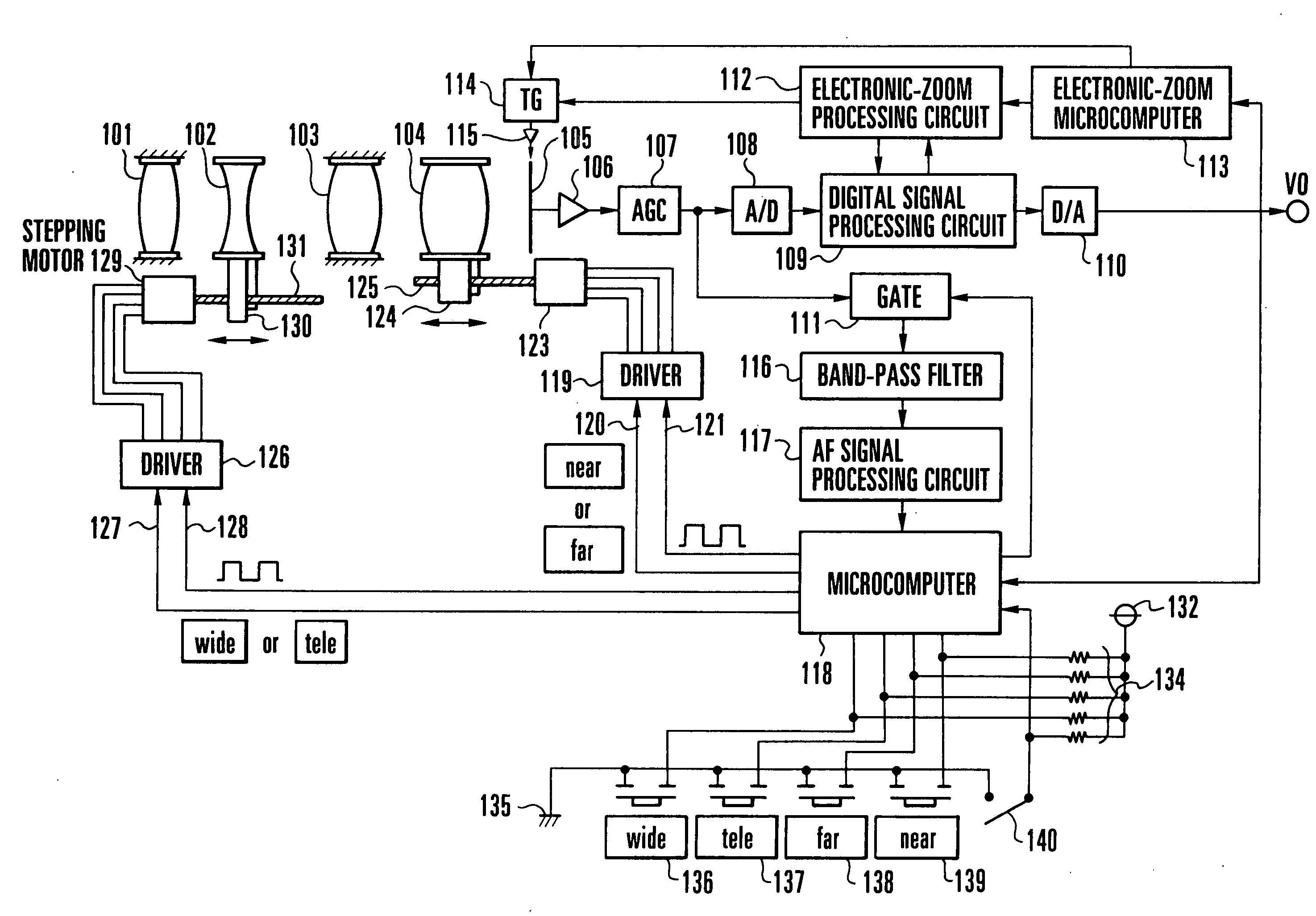
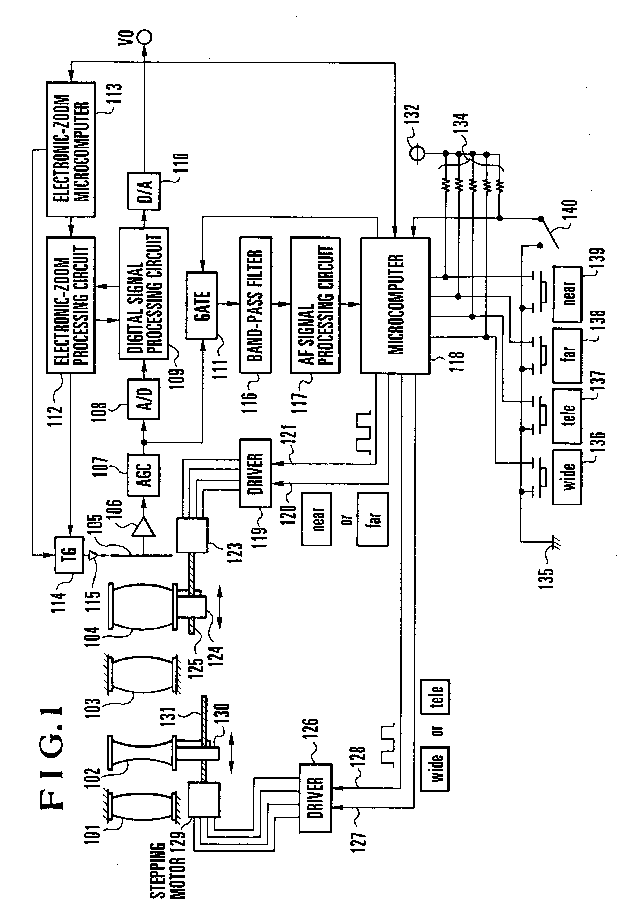
[0049]FIG. 1 is a block diagram schematically showing the arrangement of the essential parts of a first embodiment of the present invention. The following description will be made in connection with an example in which stepping motors are employed as actuators for driving a variator lens and a focusing lens.

[0050] In the arrangement shown in FIG. 1, an inner focus type of lens system is formed by constituent elements 101, 102, 103 and 104. The constituent element 101 is a first lens group which is provided as a fixed front lens group, the constituent element 102 is a second lens group for effecting magnification variation (hereinafter referred to as the “variator lens”), the constituent element 103 is a third lens group which is fixedly disposed, and the constituent element 104 is a fourth lens group provided with both a compensation function and a focusing function (hereinafter referred to as the “focusing lens”). Since the construction of the lens system does not directly relate ...

second embodiment

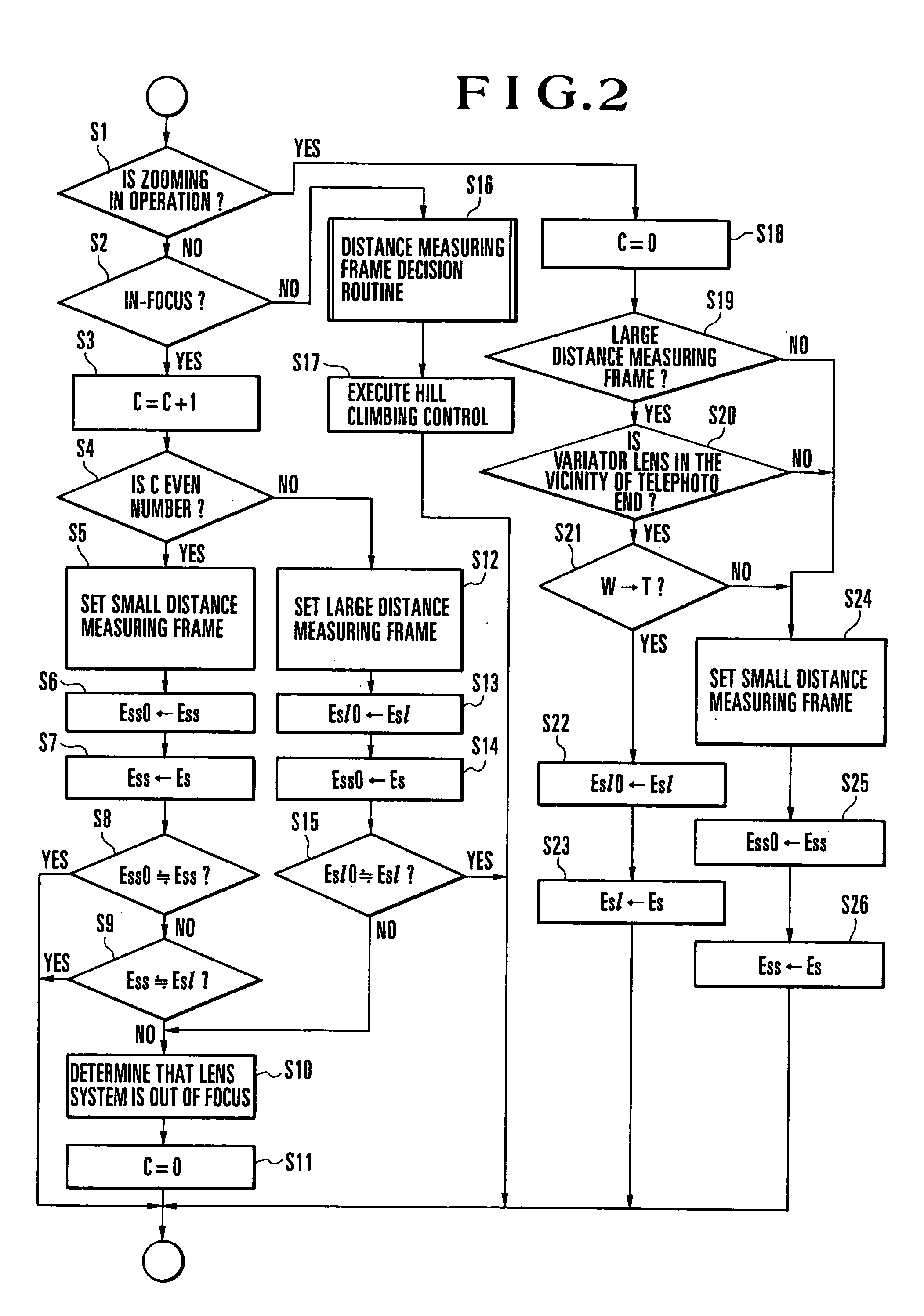
[0093] The following description is made in connection with the control of a distance measuring frame which is performed during the operation of the electronic zoom for electronically enlarging a photographic image. In the case of an arrangement provided with an electronic-zoom function, unlike an optical zoom, the angle of view of the picture of an electronically zoomed image does not always correspond to the picture of an image picked up by an image pickup device, i.e., the angle of view of the picture of the enlarged image differs from the angle of view of the picture of the image picked up by the image pickup device. Accordingly, it is necessary to set an optimum distance measuring frame by performing processing according to each individual angle of view.

[0094] There are two methods for setting a distance measuring frame from which to obtain an AF sharpness signal relative to the angle of view which is varied by the electronic zoom. One method is to extract the AF sharpness sig...

third embodiment

[0112] A third embodiment of the present invention will be described below. The third embodiment relates to a video camera provided with both optical zooming means and electronic zooming means and is intended to realize optimum control of focusing adjusting means according to the characteristics of the respective zooming means.

[0113] The recent development of video apparatuses, such as video cameras and electronic cameras, is remarkable, and a number of standard functions, such as an automatic focus adjusting (AF) function, are incorporated into a single video apparatus to improve the function and operability thereof.

[0114] In the field of automatic focus adjusting devices, the following type of system has become increasingly popular: the sharpness of a picture is detected from a video signal obtained through photoelectric conversion of a subject image by an image pickup device or the like, and the position of a focusing lens is controlled so that the sharpness becomes a maximum, ...


PUM


Abstract

A video camera includes a gate circuit for extracting a sharpness signal relative to an area which is set in a portion of a picture, a focus adjusting device for performing focus adjustment on the basis of the sharpness signal relative to the area, and an area selecting circuit for controlling the gate circuit to vary the area in size and determining a size of the area during a driving of a variator lens in accordance with a size of the area and a focal length used before the driving of the variator lens.

Description

BACKGROUND OF THE INVENTION [0001] 1. Field of the Invention [0002] The present invention relates to a video camera apparatus provided with an automatic focus adjusting device for automatically bringing a subject into focus. [0003] 2. Description of the Related Art [0004] It is known that an apparatus, such as a video camera, having a two-dimensional image pickup device utilizes a method of detecting the sharpness of a picture from a video signal of a subject, controlling the position of a focusing lens so that the sharpness becomes a maximum, and bringing the apparatus into focus. [0005] In general, to evaluate the sharpness signal, either of the following signal strengths is employed: the strength of a high-frequency component of a video signal extracted by a band-pass filter or the detection strength of a defocusing width (the width of the edge portion of a subject image) contained in a video signal extracted by a differentiating circuit or the like. In a case where an ordinary s...

Claims


Application Information

Patent Timeline
Patent Type & Authority Applications(United States)
IPC IPC(8): H04N5/232
CPCH04N5/23296H04N5/23212H04N23/673H04N23/69
Inventor HIRASAWA, MASAHIDEYAMAZAKI, TATSUYAOHKAWARA, HIROTO
Owner CANON KK
Why Eureka
Try Eureka