Base station device achieving effective use of frequencies by changing structures of antennas

a technology of antenna structure and base station, applied in the direction of electromagnetic wave modulation, transmission monitoring, polarisation/directional diversity, etc., can solve the problems of differences in characteristic characteristics affecting adaptive array characteristics, etc., to prevent deterioration of transmission/reception characteristics and effective frequency use

Active Publication Date: 2005-04-21
KYOCERA CORP
View PDF7 Cites 40 Cited by
  • Summary
  • Abstract
  • Description
  • Claims
  • Application Information

AI Technical Summary

Benefits of technology

[0012] An object of the invention is to provide a base station device, which can effectively use frequencies by changing structures of antennas, and particularly can prevent deterioration of transmission / reception characteristics.
[0017] According to the above structures, the structures of the radio units are changed to prevent deterioration of the transmission / reception characteristics in the base station device effectively utilizing the frequencies.
[0019] According to the invention, the base station device, in which the structure of the radio unit is changed for effectively utilizing frequencies, can prevent deterioration of the transmission / reception characteristics.

Problems solved by technology

However, if hardware does not have completely the same characteristics, differences in characteristic affect characteristics of the adaptive array.
Thereby, interference removal is not performed so that transmission / reception characteristics deteriorate.

Method used


Image

  • Base station device achieving effective use of frequencies by changing structures of antennas
  • Base station device achieving effective use of frequencies by changing structures of antennas
  • Base station device achieving effective use of frequencies by changing structures of antennas

Examples


Embodiment Construction

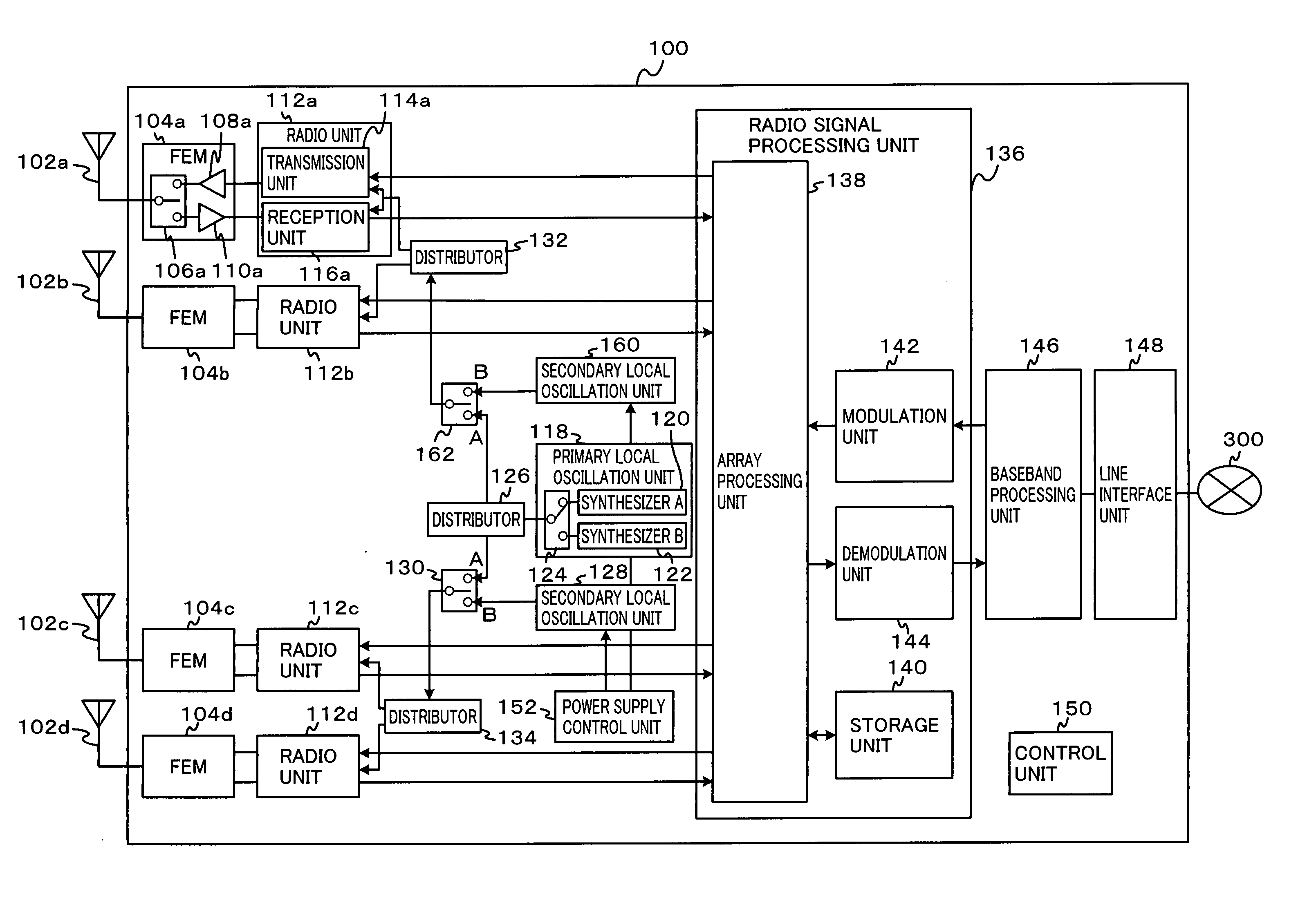
[0026] An embodiment relates to a base station device including a plurality of antennas as well as transmission / reception circuits provided for the respective antennas. The base station device has a mode, in which all the antennas are used, and a mode, in which the plurality of antennas are divided into a plurality of groups each including two or more antennas to be used independently. An array antenna pattern is formed selectively in these modes. When the array antenna pattern is to be formed in the mode of using all the antennas, a signal of one synthesizer is applied to transmission / reception circuits of all the antennas. In the mode of using antennas divided into the plurality of groups, signals of different synthesizers are supplied to the transmission / reception circuits of the antennas.

[0027] Specific examples of a base station device in a handy cellular phone system will now be described in detail.

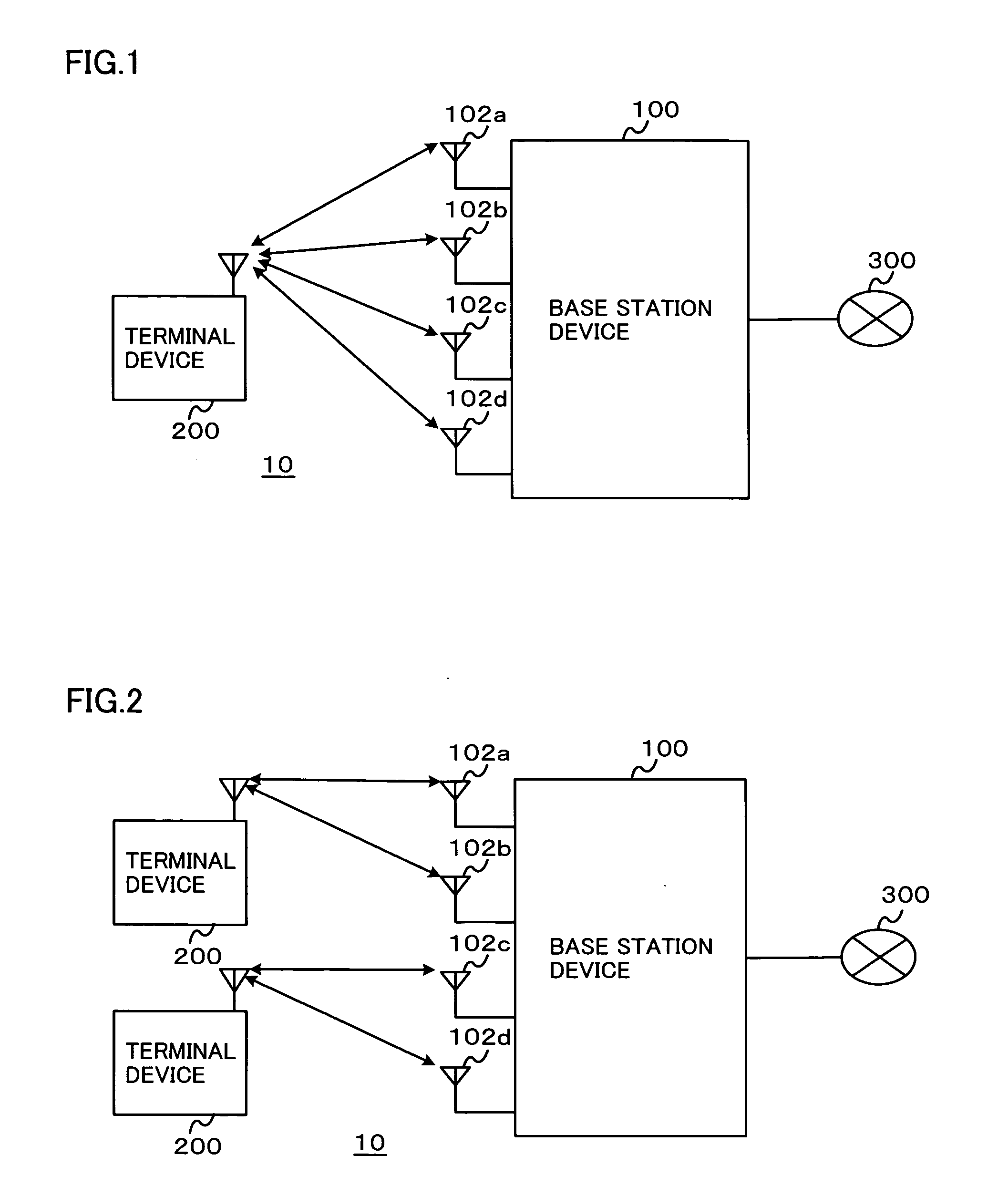
[0028]FIG. 1 shows an example of an operation state of a communication system...


PUM


Abstract

A base station device provided with a plurality of antennas has a mode, in which all the antennas are used, and a mode, in which the plurality of antennas are divided into a plurality of groups each including two or more antennas to be used independently. An array antenna pattern is formed selectively in these modes. When the array antenna pattern is to be formed in the mode of using all the antennas, a signal of one synthesizer is applied to transmission / reception circuits of all the antennas. In the mode of using antennas divided into the plurality of groups, signals of different synthesizers are supplied to the transmission / reception circuits of the antennas.

Description

BACKGROUND OF THE INVENTION [0001] 1. Field of the Invention [0002] The present invention relates to a base station device, and particularly to a base station device provided with a plurality of antennas. [0003] 2. Description of the Background Art [0004] Cellular phone systems and handy cellular phone systems are now in widespread use among many users. In these systems, terminal devices perform predetermined data communication over channels allocated by a base station device. One base station device allocates a plurality of channels to terminal devices, and multiplexes these terminals. Particularly, the cellular phone systems and handy cellular phone systems generally use a TDMA (Time Division Multiple Access) system as a multiplexing technique. According to the TDMA system, a time axis is divided into predetermined time periods called “time slots”, and these times slots are allocated to the respective users for multiplexing. [0005] An antenna directivity control technique based on...

Claims


Application Information

Patent Timeline
Patent Type & Authority Applications(United States)
IPC IPC(8): H01Q1/24H04B7/08H01Q3/24H01Q3/26H01Q5/00H01Q25/00H04B1/38H04B7/04H04B7/06H04B7/10H04B7/26H04W16/28H04W28/18
CPCH01Q1/246H01Q3/24H04B7/0874H01Q25/002H04B7/0691H01Q3/26
Inventor NARITA, MASAHIRO
Owner KYOCERA CORP
Why Eureka
Try Eureka