Communication system, communication device and communication method that can improve frequency use efficiency

a communication system and frequency efficiency technology, applied in the field of communication systems, can solve the problem that the ofdma scheme is not suitable as a transmission scheme, and achieve the effect of effective frequency us

Inactive Publication Date: 2014-07-15
SHARP KK
View PDF14 Cites 0 Cited by
  • Summary
  • Abstract
  • Description
  • Claims
  • Application Information

AI Technical Summary

Benefits of technology

[0044]A communication system, a communication device and a communication method of the present invention can increase the number of users (the number of subcarriers) capable of being accommodated while maintaining the transmission rate per user (subchannel), and can effectively use a frequency.

Problems solved by technology

The OFDMA scheme is not suitable as a transmission scheme in which a transmission power limit is strict, since the OFDMA scheme has a high peak-to-average power ratio (PAPR) characteristic.

Method used


Image

  • Communication system, communication device and communication method that can improve frequency use efficiency
  • Communication system, communication device and communication method that can improve frequency use efficiency
  • Communication system, communication device and communication method that can improve frequency use efficiency

Examples


first embodiment

[0101](First Embodiment)

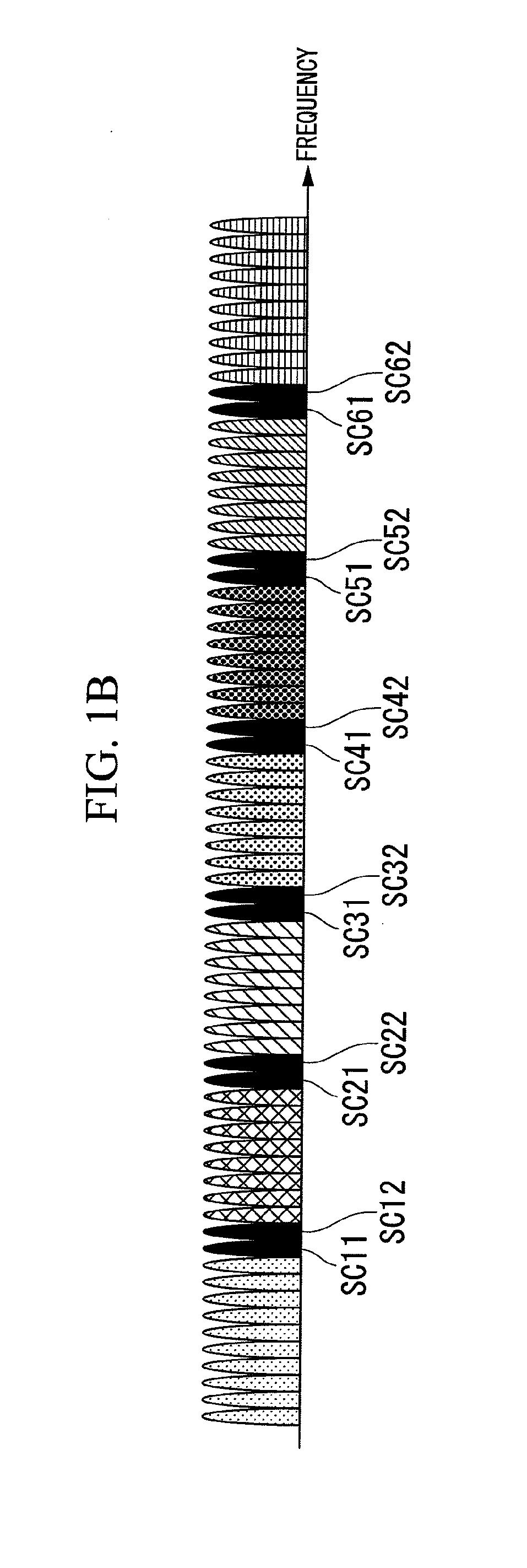
[0102]According to a first embodiment of the present invention, a communication system includes a terminal device (also referred to as a first communication device) and a base station device (also referred to as a second communication device). In this embodiment, some subcarriers of a subchannel used by the terminal device are also used in another terminal device. The terminal device transmits data using subchannels notified from the base station device. Thus, the terminal device of this embodiment may have the same configuration as a terminal device (FIG. 14) of the related art. The configuration of the base station device will be described later in second and third embodiments. In the present embodiment, a subchannel arrangement in a system in which some subcarriers within a subchannel are used in an overlapping manner with a user allocated to another subchannel will be described.

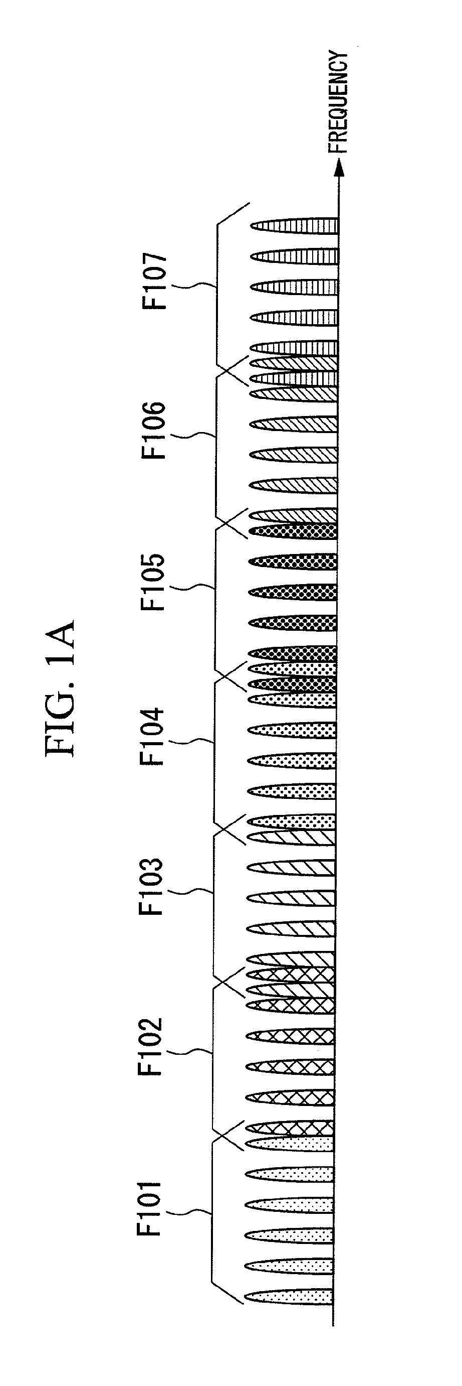
[0103]FIG. 1A shows an example of an arrangement of pilot signals according to...

second embodiment

[0141](Second Embodiment)

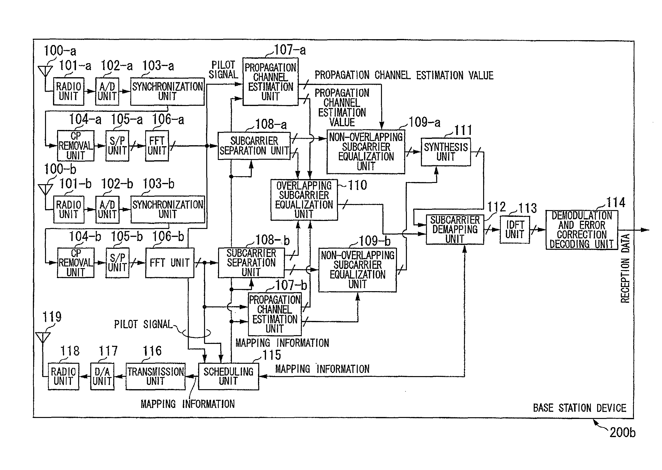
[0142]Next, the configuration of a base station device 200b in a communication system according to a second embodiment of the present invention will be described.

[0143]FIG. 4 is a schematic block diagram showing the configuration of the base station device 200b according to the second embodiment of the present invention. As shown in FIG. 4, the base station device 200b according to this embodiment includes reception antennas 100-a and 100-b, radio units 101-a and 101-b, A / D conversion units 102-a and 102-b, synchronization units 103-a and 103-b, CP removal units 104-a and 104-b, S / P conversion units 105-a and 105-b, FFT units 106-a and 106-b, propagation channel estimation units 107-a and 107-b, subcarrier separation units 108-a and 108-b, non-overlapping subcarrier equalization units 109-a and 109-b, an overlapping subcarrier equalization unit 110, a synthesis unit 111, a subcarrier demapping unit 112, an IDFT unit 113, a demodulation and error correction d...

third embodiment

[0168

[0169]In the second embodiment, the base station device 200b (FIG. 4) has the plurality of reception antennas 100-a and 100-b. The signal separation has been performed by MIMO-processing the subcarriers used in an overlapping manner between the subchannels.

[0170]On the other hand, in the present embodiment, the case where signal separation can be performed even when the number of reception antennas is 1, by using non-linear iterative equalization, will be described.

[0171]FIG. 5 is a schematic block diagram showing the configuration of a base station device 200c according to the third embodiment of the present invention. The same reference numerals are assigned to the same blocks as those of the base station device 200b of FIG. 4. Since the transmission system is the same as that shown in FIG. 4, the illustration thereof is omitted.

[0172]As shown in FIG. 5, the reception system of the base station device 200c according to the present embodiment includes a reception antenna 100, ...


PUM


Abstract

A communication system that transmits a signal from a first communication device to a second communication device using a plurality of frequency channels, wherein at least one of the plurality of frequency channels uses part of subcarriers in an overlapping manner with one or more adjacent frequency channels, the first communication device includes a transmission unit which transmits a signal to the second communication device using one or more of the plurality of frequency channels, and the second communication device includes a reception unit which receives the signal transmitted by the transmission unit.

Description

TECHNICAL FIELD[0001]The present invention relates to a communication system, a communication device and a communication method.[0002]This application claims priority to and the benefits of Japanese Patent Application No. 2008-055133 filed on Mar. 5, 2008, the contents of which are incorporated herein by reference.BACKGROUND ART[0003]With the recent increase in the amount of data communication, there is a growing need for mobile communication systems having higher frequency use efficiency. Thus, one-cell reuse cellular systems using the same frequency band in all cells are being studied.[0004]An evolved universal terrestrial radio access (E-UTRA) system is one of the one-cell reuse cellular systems, and is being standardized mainly in 3rd Generation Partnership Project (3GPP). In the E-UTRA system, the use of an orthogonal frequency division multiple access (OFDMA) scheme is being studied as a downlink transmission scheme. Also, in the E-UTRA system, the use of a single carrier-freq...

Claims


Application Information

Patent Timeline
Patent Type & Authority Patents(United States)
IPC IPC(8): H04W4/00
CPCH04L5/0044H04L5/0037H04L5/0048H04L25/03159H04L5/0007H04L2025/03426H04L5/0023H04L27/156H04L25/0226H04J11/004
Inventor TO, SHIMPEIKUBOTA, MINORUHAMAGUCHI, YASUHIRONAMBA, HIDEOYOKOMAKURA, KAZUNARI
Owner SHARP KK
Why Eureka
Try Eureka