
Relay apparatus for broadcast waves

a relay apparatus and broadcast wave technology, applied in the field of relay apparatus for relaying broadcast waves, can solve the problems of difficult to perform stably a multi-stage relay in an sfn environment in an urban region or a mountain region similar to the above, and achieve the effect of high quality and effective use of radio waves

Active Publication Date: 2014-06-12
KOKUSA ELECTRIC CO LTD
View PDF1 Cites 0 Cited by
  • Summary
  • Abstract
  • Description
  • Claims
  • Application Information

AI Technical Summary

Benefits of technology

The present invention allows for effective use of frequencies to prevent wraparound effects and allows for high-quality area broadcasting through multistage relay. By shifting frequencies within one transmission channel, a relay transmission system can be created that can construct SFN without receiving effects due to wraparound.

Problems solved by technology

However, for digital terrestrial broadcasting, if the transmission station (master station, higher rank station) or the relay transmission station (relay station) is located in an urban region or a mountain region, as shown in FIG. 12, radio reflections are many due to vehicular traffic in the urban region, buildings or mountains, and it is difficult to construct the SFN environment by multistage relay of broadcast waves.
For example, it is difficult for a wraparound canceller to be used in the transmission station of digital terrestrial broadcasting to cancel the wraparound wave stably and continuously to transmit a broadcast wave signal (retransmitted wave) to a subsequent stage because a change in received signal level of broadcast waves due to the influence of radio reflection and a change in a number of multipath waves and a D / U ratio are considerable.
Even when such one-segment broadcasting service of digital terrestrial broadcasting is performed, it is difficult to perform stably a multistage relay in an SFN environment in an urban region or a mountain region similar to the above.

Method used


Image

  • Relay apparatus for broadcast waves
  • Relay apparatus for broadcast waves
  • Relay apparatus for broadcast waves

Examples


Embodiment Construction

[0045]The present invention is described specifically according to the embodiments shown in the drawings.

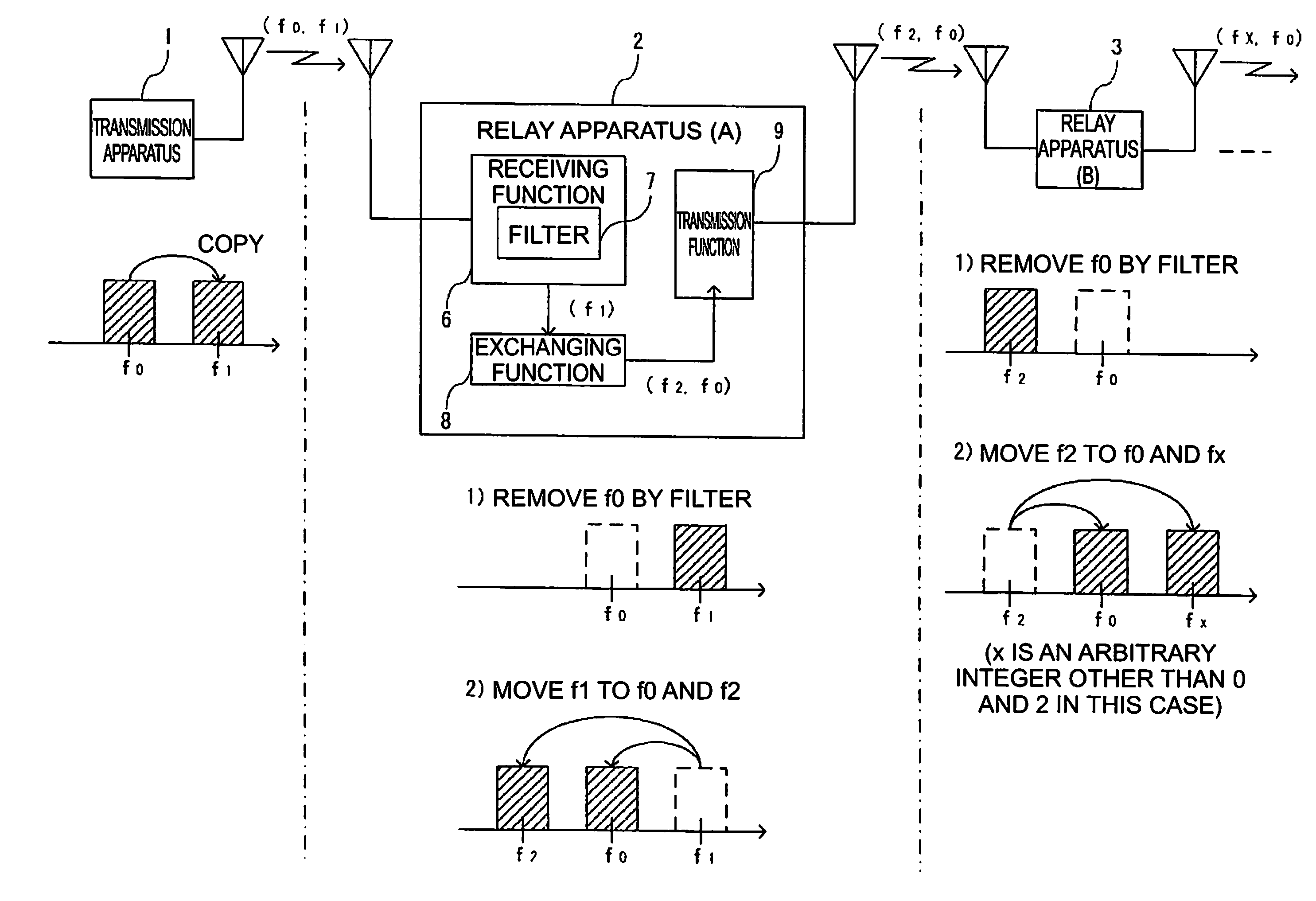
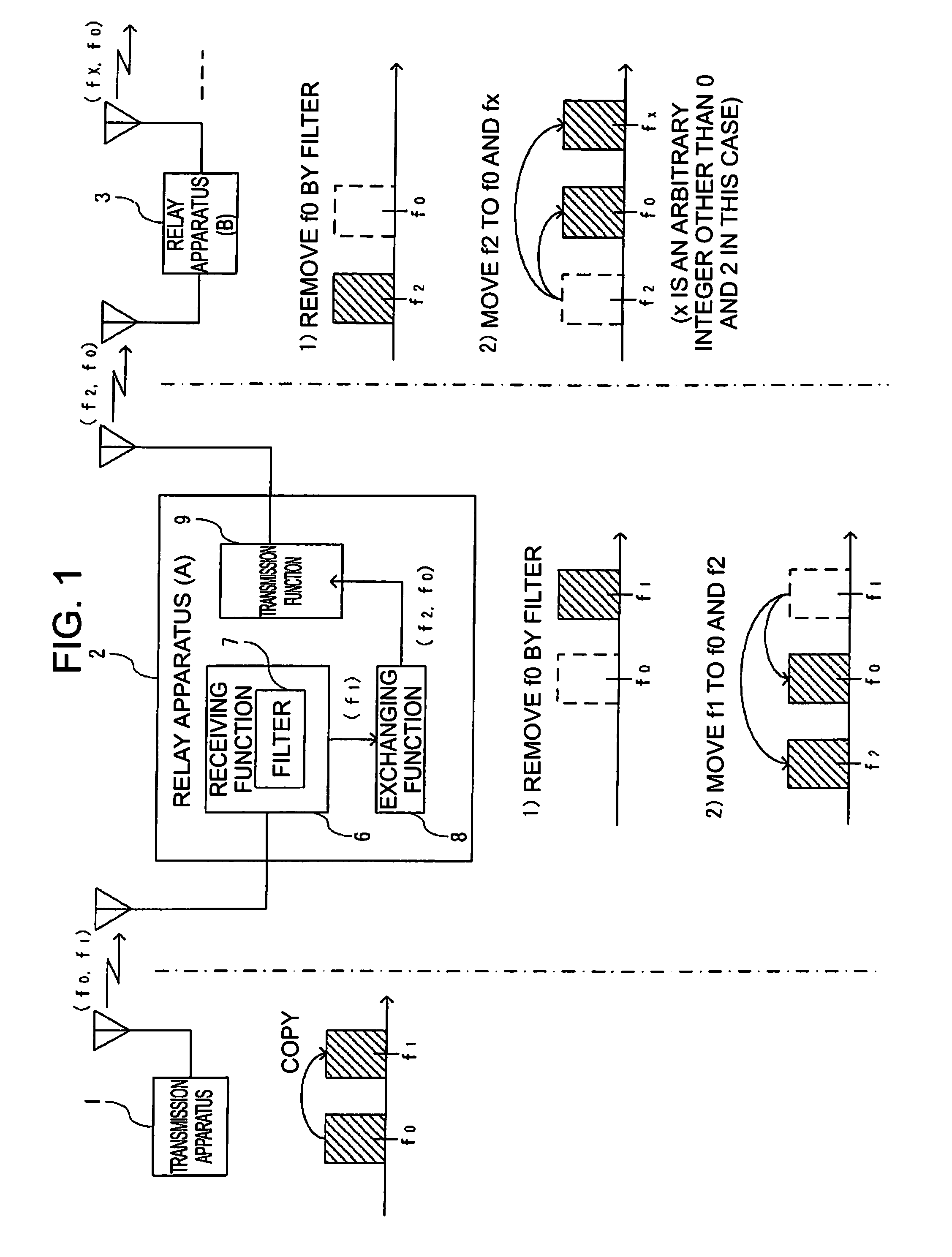
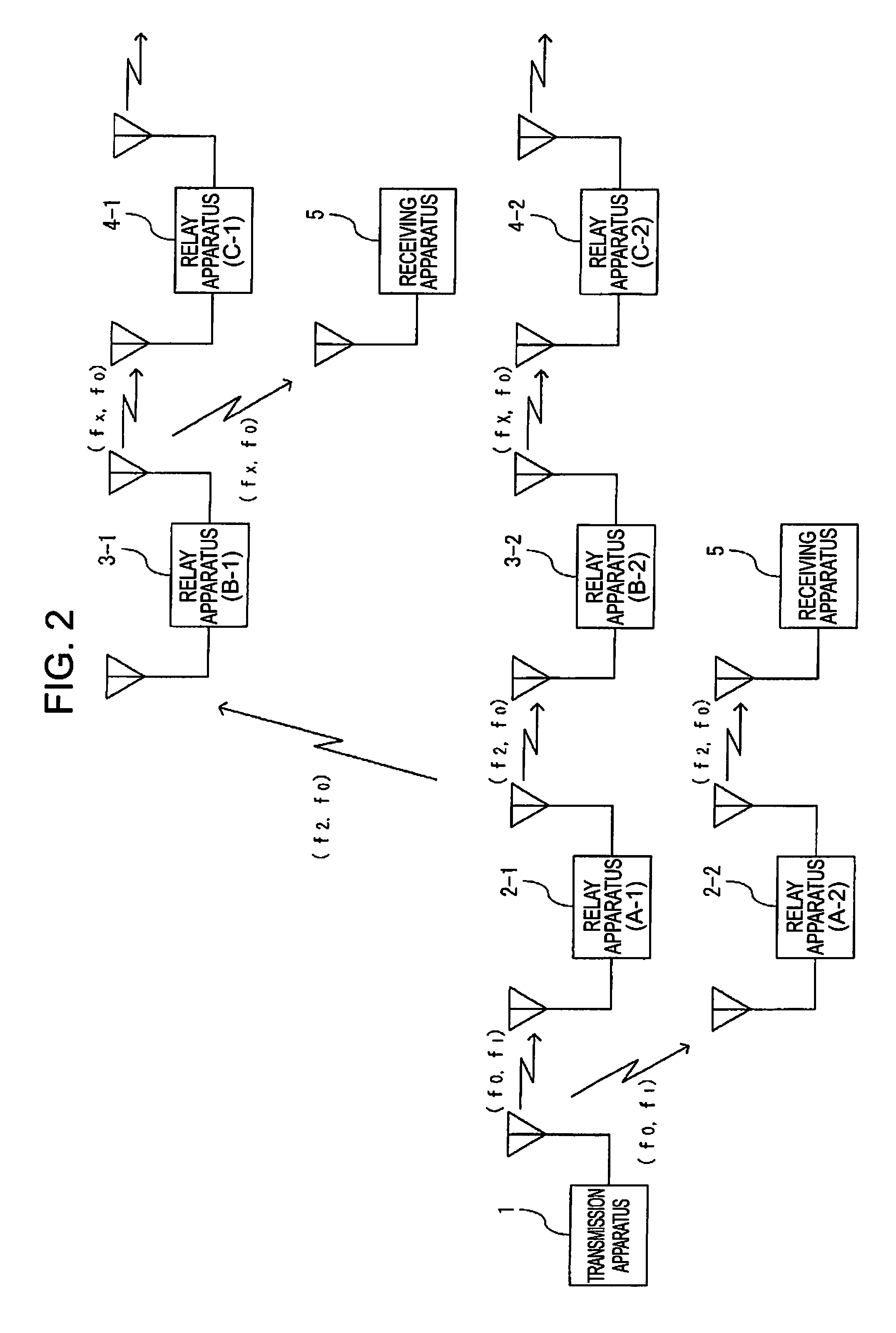
[0046]FIG. 1 and FIG. 2 show a relay transmission system for broadcast waves according to one embodiment of the present invention.

[0047]FIG. 1 shows a basic structure of a relay transmission system that performs multistage relay, and the relay transmission system performs transmission of the broadcast waves transmitted from a transmission apparatus 1 by sequentially relaying via a relay apparatus (A)2, a relay apparatus (B)3, . . . .

[0048]This relay transmission system performs transmission of terrestrial digital broadcast waves of a one-segment method that performs transmission of broadcast waves in which broadcast data are placed in a specific segment (defined segment: f0) within a transmission channel, and also uses other segments (f1, f2, . . . fx) to perform transmission of this broadcast data.

[0049]Therefore, the transmission apparatus 1 has a function to copy and place the...


PUM


Abstract

The objective of the present invention is to provide a relay apparatus capable of performing normal relay transmission for broadcast waves by preventing effects caused by wraparound in a relay apparatus. For broadcast waves received by a relay apparatus (2), the same broadcast data are placed in each of a defined segment (f0) and a first segment (f1) other than the defined segment, whereupon the relay apparatus removes broadcast data for the defined segment (f0) from the received broadcast waves, and transmits broadcast waves in which the broadcast data for the first segment (f1) have been exchanged with each of the defined segment (f0) and a second segment (f2) other than the defined segment and the first segment. As a result, the defined segment (f0) which imparts wraparound effects to the received broadcast waves is removed, and therefore, it is possible to perform normal relay transmission of the broadcast waves.

Description

TECHNICAL FIELD[0001]The present invention relates to a relay apparatus for relaying broadcast waves in which broadcast data are placed in a defined segment (frequency) and to a technology suitably used for an area broadcasting system covering a comparatively small specific area (for example, an event site) using a one-segment broadcasting system.BACKGROUND ART[0002]One-segment broadcasting is one type of digital terrestrial broadcasting ISDB-T (Integrated Services Digital Broadcasting-Terrestrial), and it is one type of partial segment broadcasting that performs transmission of broadcast waves in which broadcast data are placed in a specific frequency (segment) within a transmission channel and is being used for broadcasting to mobile terminals and the like. A method of broadcasting in a partial segment of the number of all segments in a transmission channel for SDTV (Standard Definition Tele-Vision) broadcasting such as the one-segment broadcasting, so-called digital radio broadca...

Claims


Application Information

Patent Timeline
IPC IPC(8): H04B7/155H04H20/06
CPCH04H20/06H04H20/67H04B7/15528H04B7/15507H04B7/14
Inventor SAKATA, SATOSHIABE, JUNOTOSAKA, OSAMUWATANABE, MAKOTOCHIBAZAKI, MOTOKIYOSHII, KAZUHIKO
Owner KOKUSA ELECTRIC CO LTD
Learn More