

Ultrasonic image processor and ultrasonic diagnostic instrument
a diagnostic instrument and ultrasonic technology, applied in ultrasonic/sonic/infrasonic image/data processing, instruments, tomography, etc., can solve the problems of inability to avoid contradictions in above techniques, substantially complex movement of the whole heart, etc., to improve tissue tracking imaging and high clinical applicability.
- Summary
- Abstract
- Description
- Claims
- Application Information
AI Technical Summary
Benefits of technology
Problems solved by technology
Method used
Image

Examples
first embodiment
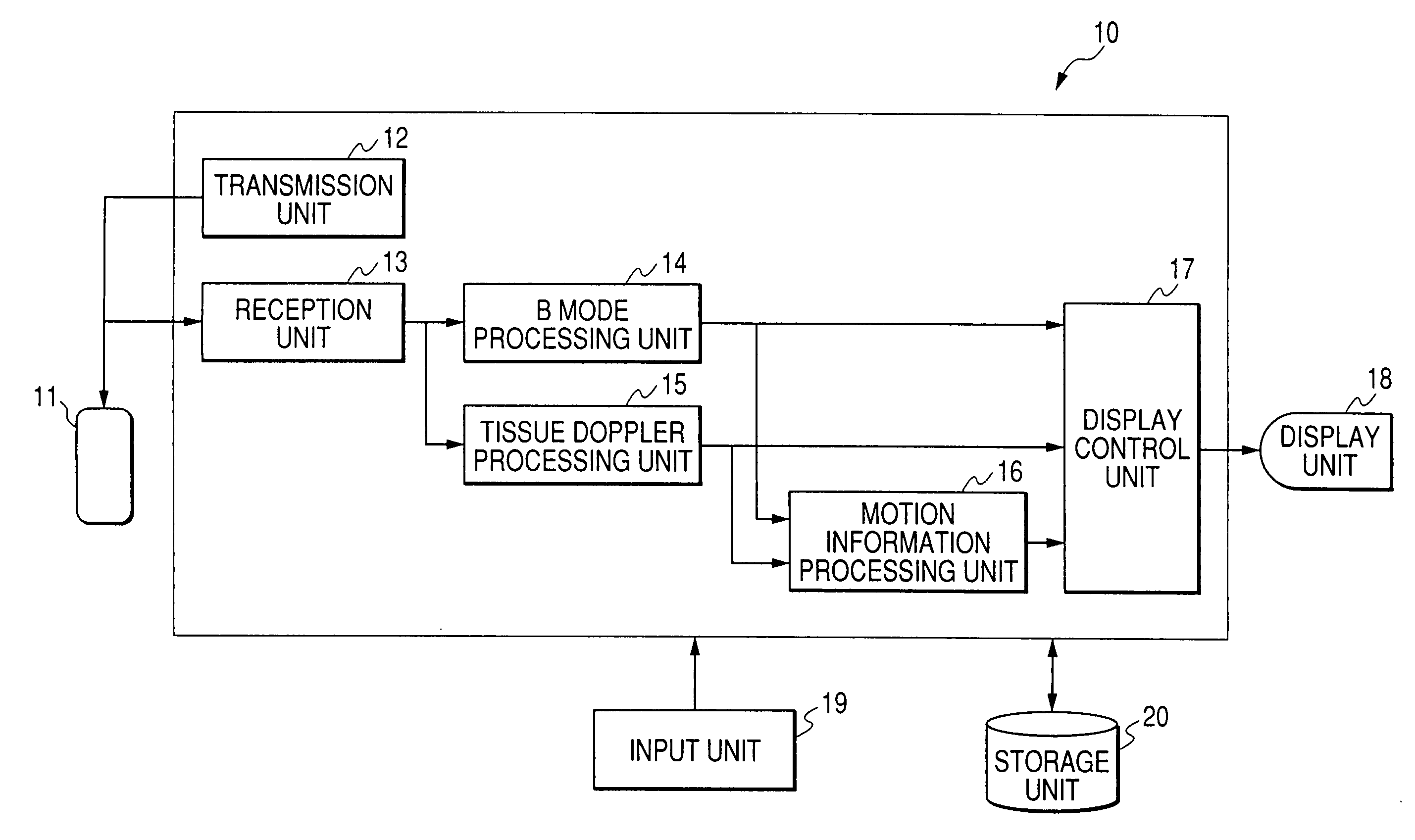
[0047]FIG. 2A is a block diagram illustrating a structure of an ultrasonic diagnostic instrument 10 according to a first embodiment of the present invention. The ultrasonic diagnostic instrument 10 comprises an ultrasonic probe 11, a transmission unit 12, a reception unit 13, a B mode processing unit 14, a tissue Doppler processing unit 15, a motion information processing unit 16, a display control unit 17, a display unit 18, an input unit 19, and a storage unit 20.
[0048] The ultrasonic probe 11 comprises a plurality of piezoelectric vibrators for generating an ultrasonic wave in response to a driving signal from the transmission unit 12 and converting the reflected wave from a sample into an electrical signal, a matching layer provided in each piezoelectric vibrator, and a packing member for preventing the ultrasonic wave from propagating toward the rear side from each piezoelectric vibrator. When the ultrasonic wave is transmitted to the sample from the ultrasonic probe 11, vario...
second embodiment
[0101] Next, a second embodiment of the present invention will be described. The second embodiment utilizes velocity distribution images generated by performing the pattern matching process to a plurality of two-dimensional tissue images at a plurality of time phases collected in the B mode, etc.
[0102]FIG. 8 is a block diagram illustrating a construction of an ultrasonic diagnostic instrument 10 according to this embodiment. FIG. 8 is substantially equal to FIG. 2A, except that the tissue Doppler processing unit 15 is replaced with a motion vector processing unit 30.
[0103] The motion vector processing unit 30 detects a moved position of a tissue between two ultrasonic tissue images (for example, B mode images) having different time phases using the pattern matching process, and calculates a tissue velocity on the basis of the moved position. Specifically, the motion vector processing unit extracts a partial image from a first ultrasonic image and obtains a position having highest ...
third embodiment
[0117] Next, a third embodiment will be described. In the third embodiment, more effective motion information images are generated, by using both the velocity distribution image generated from the ultrasonic image data at a plurality of time phases collected through the tissue Doppler method and the velocity distribution image obtained by performing the pattern matching process to a plurality of two-dimensional tissue images at a plurality of time phases collected through the B mode method, etc.
[0118]FIG. 11 is a block diagram illustrating a construction of the ultrasonic diagnostic instrument 10 according to this embodiment. In FIG. 11, the ultrasonic diagnostic instrument comprises both the tissue Doppler processing unit 15 and the motion vector processing unit 30.
[0119] The motion information processing unit 16 generates the motion information image in accordance with a synthesis function of the tissue Doppler method and the pattern matching method (hereinafter, simply referred...
PUM
 Abstract
Description
Claims
Application Information