Lancet assembly

Inactive Publication Date: 2005-04-21
SURGILANCE
View PDF3 Cites 137 Cited by
  • Summary
  • Abstract
  • Description
  • Claims
  • Application Information

AI Technical Summary

Benefits of technology

[0006] Briefly described, in a preferred form, the present invention is an improvement over the conventional lancet assembly by providing in one aspect a lancet assembly having a distal end, a proximal end and a longitudinal axis running there between. The triggler is partially inserted into a housing from the distal end. The housing is provided with a rigid internal spring holder to receive a spring-loaded lancet structure. The lancet structure is provided with a body coupled to a spring which extend from the proximal end of the body. A lancet is attached to the body with the sharp tip pointing towards the distal end. The triggler interacts with the housing via a triggering element to maintain the spring in a compressed state such that the lancet stru

Problems solved by technology

This compresses the assembly and causes firin

Method used


Image

  • Lancet assembly
  • Lancet assembly
  • Lancet assembly

Examples


Embodiment Construction

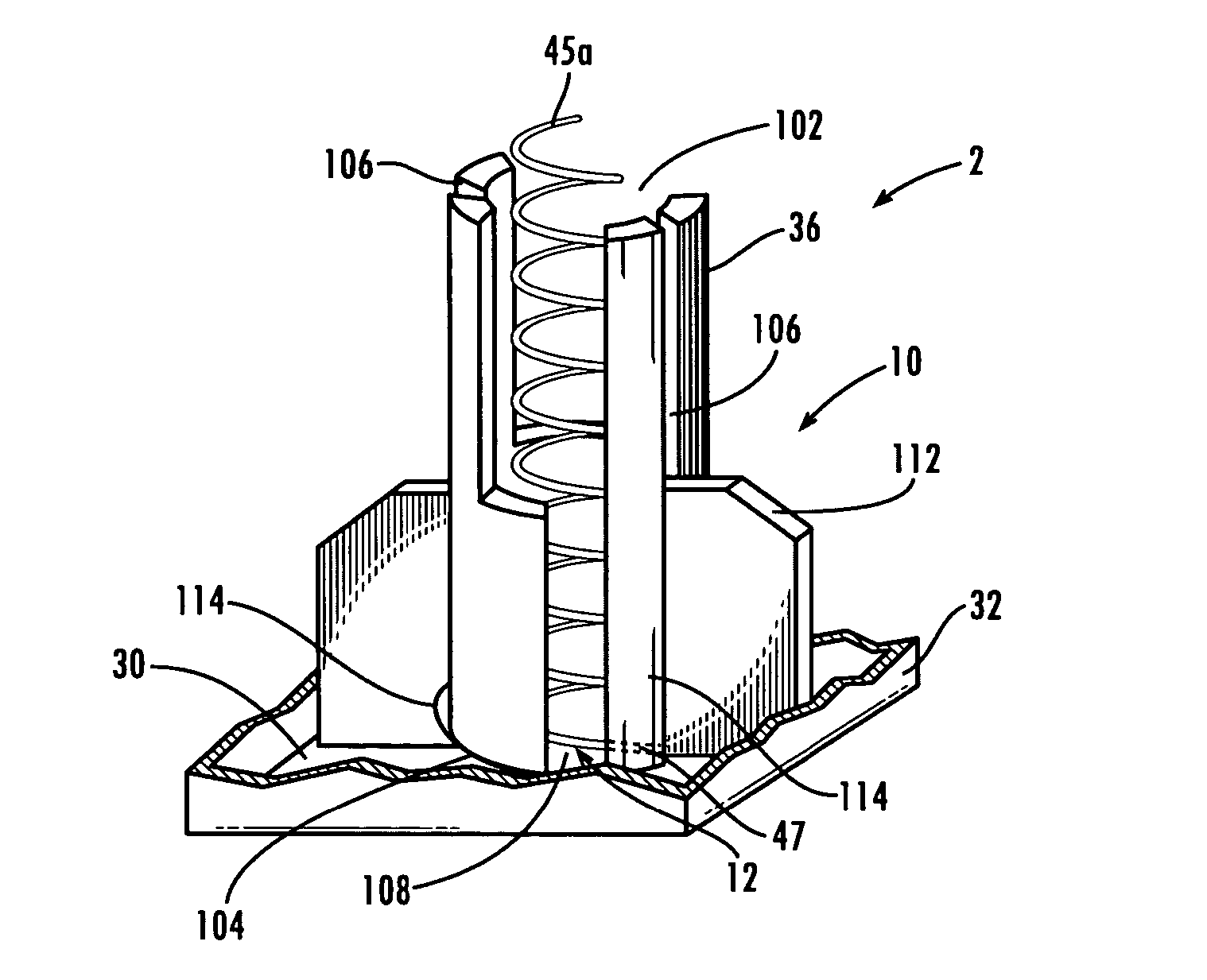
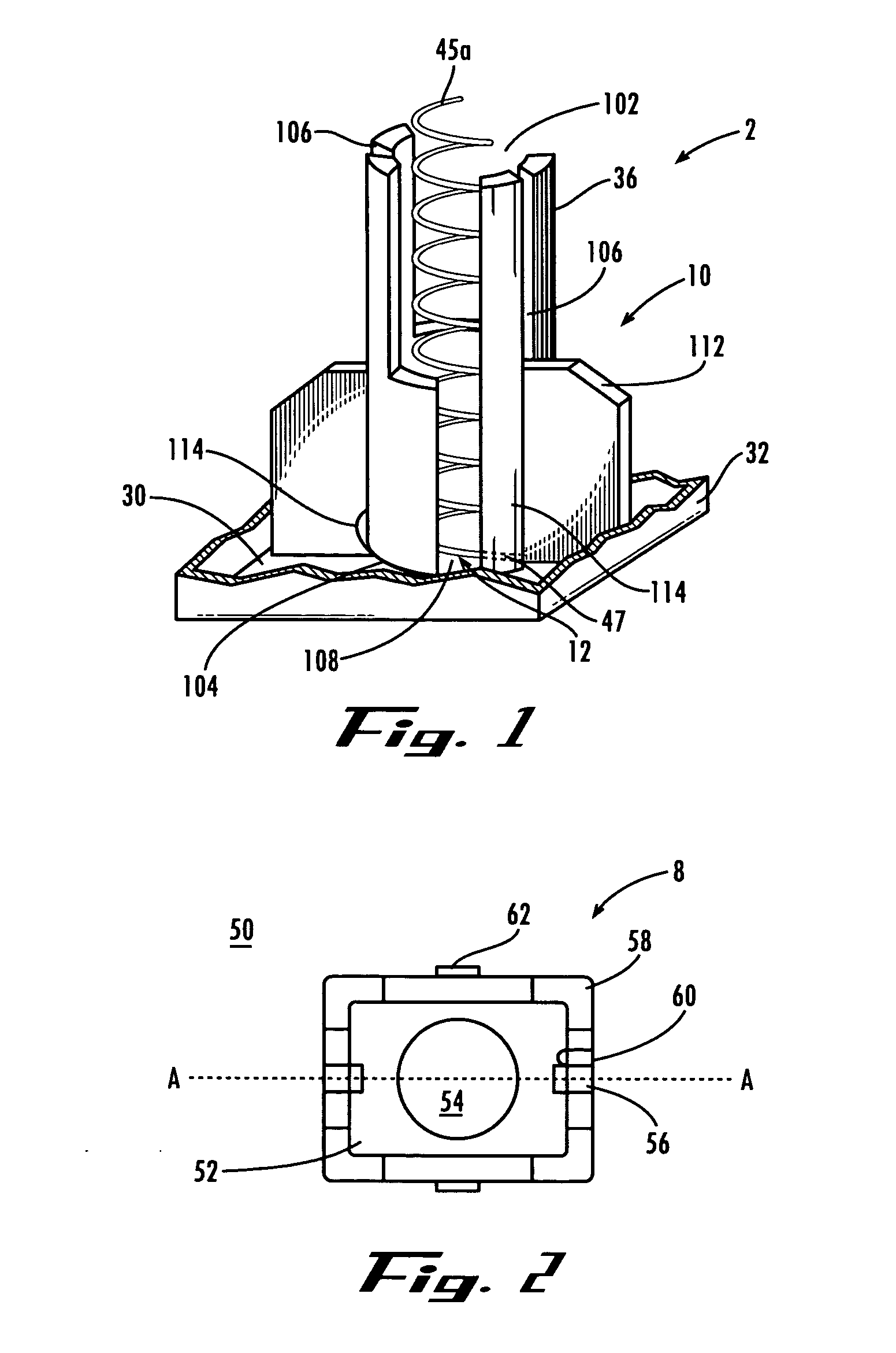
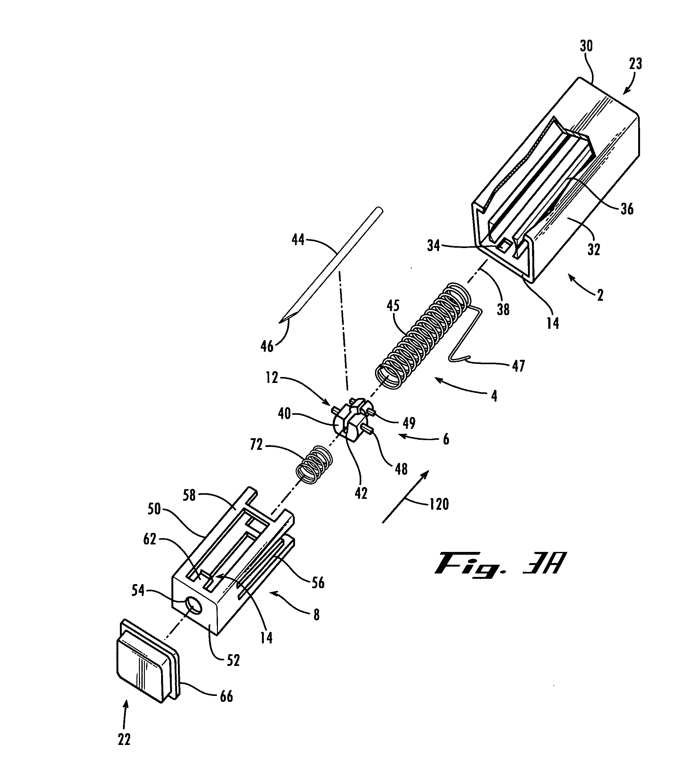
[0020] Referring now in detail to the figures, wherein like reference numerals represent like parts throughout the several views, the present lancet assembly comprises a housing 2, firing element 4, lancet system 6, triggering element 8, and release system 10. The device is preferably pre-armed; that is, the device needs no arming by the user, just a light push on the triggering element 8 (preferably triggler 50) activates the release system 10, which releases the firing element 4 (preferably a spring 45), extending the lancet system 6, and the skin is pierced.

[0021] The present lancet assembly has a longitudinal axis defined by the axis of compression of the spring 45. The triggler 50 (or triggering device) and housing 2 interact by keeping the spring 45 in a standby, compressed, pre-armed state. Upon compression of the assembly along the longitudinal axis by the user pressing the end wall of the triggler onto the skin of a patient, the lancet will be fired to pierce the skin.

[00...


PUM


Abstract

A lancet assembly having a lancet holder and a triggler enclosing a lancet structure. The triggler is partially inserted into a lancet holder from the distal end. The holder is provided with a rigid internal spring holder to receive the spring-loaded lancet structure. The lancet structure is provided with a body coupled to a spring which extend from the proximal end of the body. The spring has a linear axis of compression which coincide with the longitudinal axis of the lancet assembly. A lancet is attached to the body with the sharp tip pointing towards the distal end. The triggler interacts with the lancet holder via a triggering element to maintain the spring in a compressed state such that the lancet structure is in a stable standby position which is not easily triggered by accidental bumps on the assembly. Upon firing, a second spring dampens the extension of the sharp tip, and ultimately assists in the retraction of the tip back into the assembly.

Description

RELATED US APPLICATION DATA [0001] This application claims priority from U.S. Provisional Application No. 60 / 511,230 filed Oct. 15, 2003.FIELD OF THE INVENTION [0002] The present invention is related to finger-pricking devices. In particular, the present invention is related to lancets for medical use. BACKGROUND OF THE INVENTION [0003] Lancets or finger-pricking devices are used in the medical field for applications such as skin incisions and blood drawing. In some lancet assemblies, the blade or needle is kept in a standby position until it is triggered by the user, who is typically medical personnel in charge of drawing the blood from a patient. In other lancet assemblies, the user has to manually set the assembly to an armed position before firing can be triggered. Upon triggering, the blade fires onto the skin of the patient, for example on the finger, and makes an incision. [0004] Such prior art lancet assemblies must be sterilized before use, and the lancet maintained under s...

Claims


Application Information

Patent Timeline
IPC IPC(8): A61B5/15
CPCA61B5/15142A61B5/1411A61B5/150022A61B5/150412A61B5/150717A61B5/150885A61B5/15111A61B5/15117A61B5/1513A61B5/15144
Inventor YI, PATRICKFOO, KOOK-TING
Owner SURGILANCE
Why Eureka
Try Eureka