Automatic suture locking device

a technology of automatic locking and suture, which is applied in the field of vascular closure devices, can solve the problems of difficult manufacture and difficult deployment of slipknots by doctors, and achieve the effect of preventing free suture movemen

Active Publication Date: 2005-04-21
TERUMO PUERTO RICO L L C
View PDF30 Cites 310 Cited by
  • Summary
  • Abstract
  • Description
  • Claims
  • Application Information

AI Technical Summary

Benefits of technology

[0005] To attain the advantages and in accordance with the purpose of the invention, as embodied and broadly described herein, an automatic suture locking assembly is provided. The suture locking assembly generally compr...

Problems solved by technology

Along with other problems, the slipknot can be difficult...

Method used


Image

  • Automatic suture locking device
  • Automatic suture locking device
  • Automatic suture locking device

Examples


Embodiment Construction

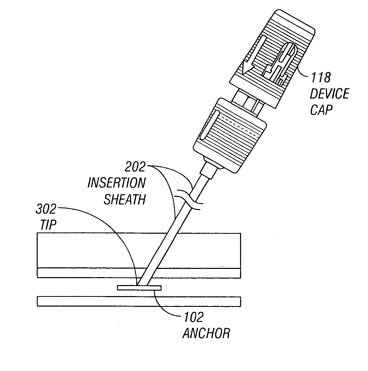
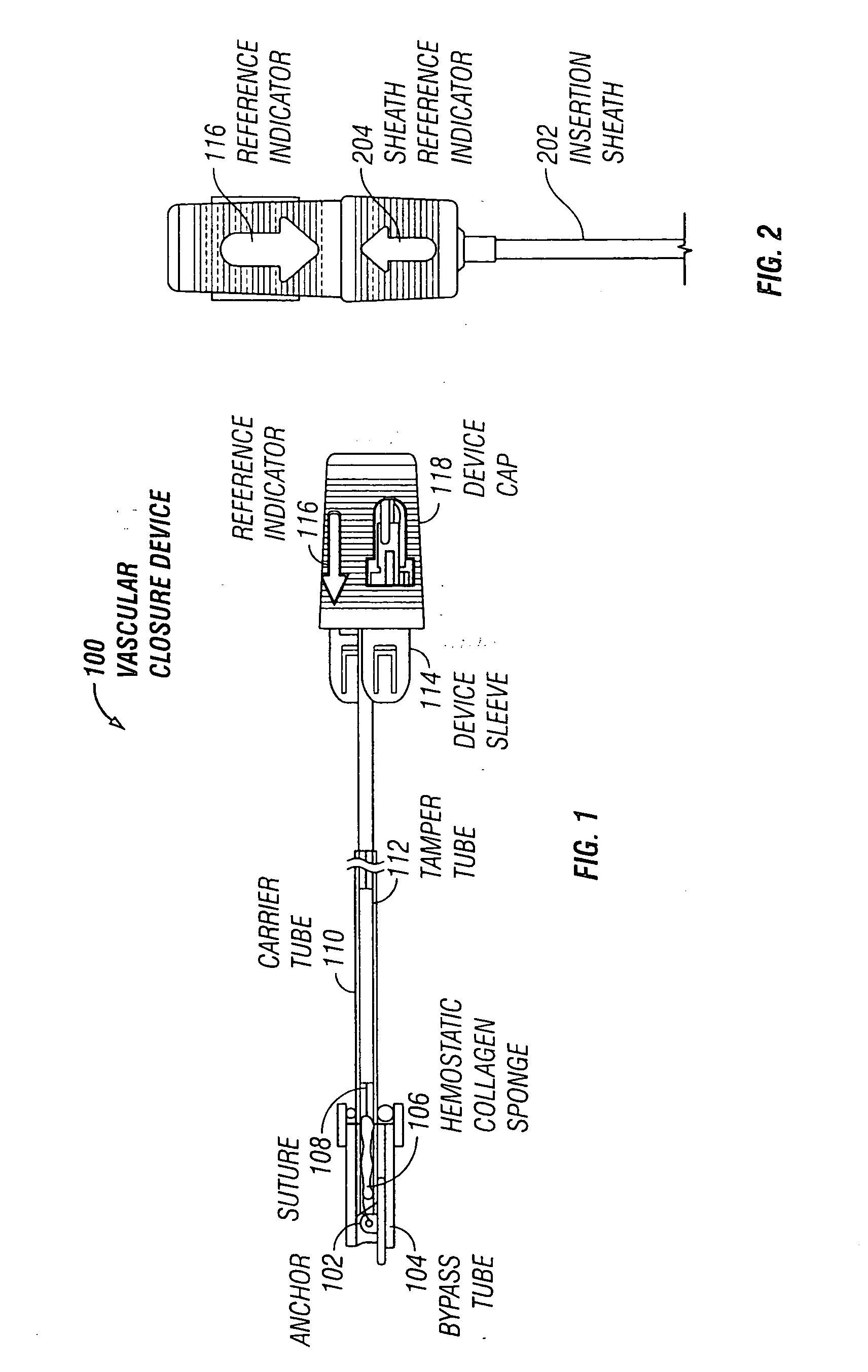
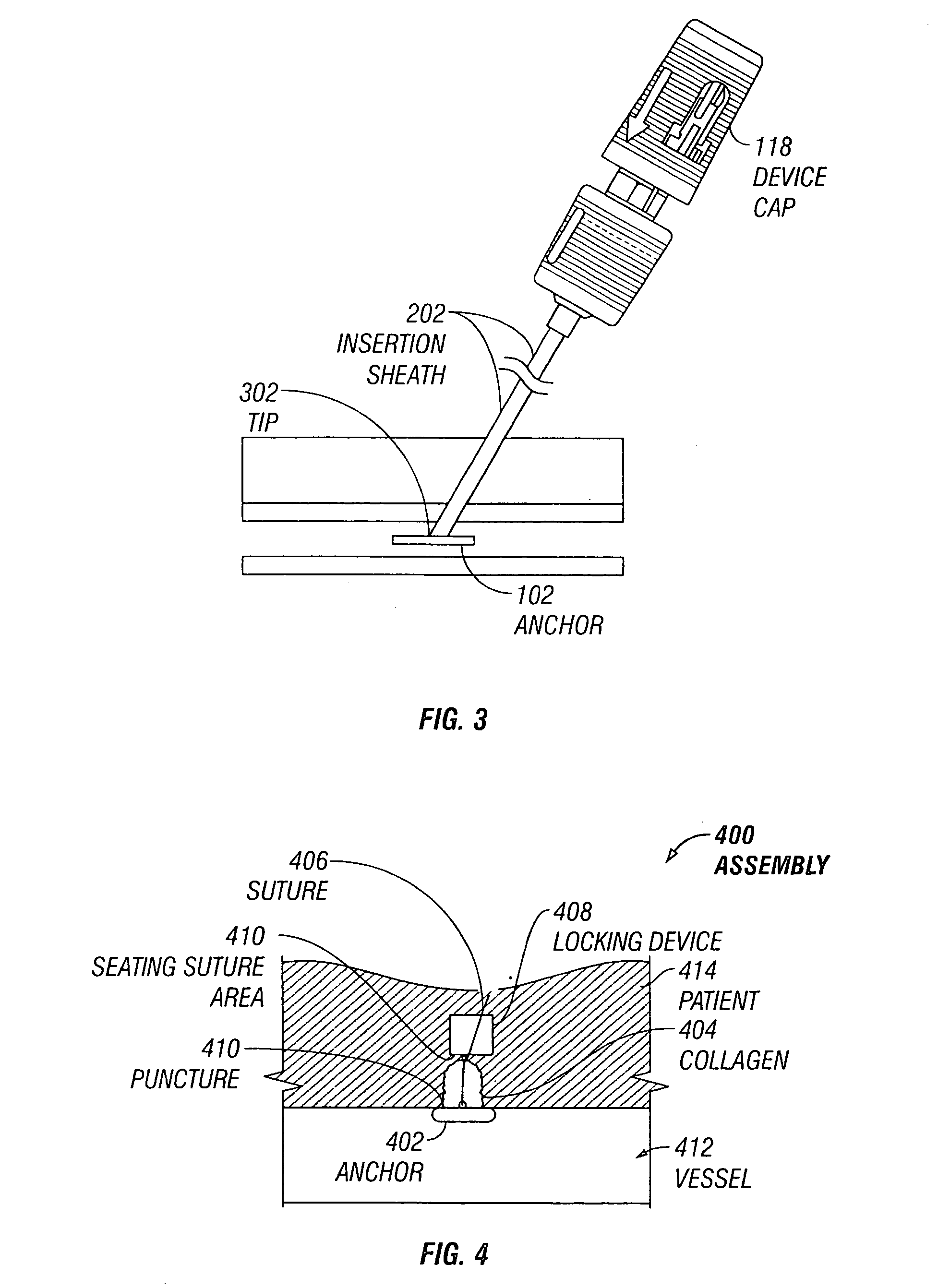
[0015] The present invention will now be described with reference to FIGS. 4-7C. Referring to FIG. 4, an assembly 400 consistent with the present invention is shown. Assembly 400 includes an anchor 402, a collagen 404, a suture 406, and an automatic locking device 408. Assembly 400 is shown deployed to close a puncture 410 in a vessel 412 of a patient 414. Largely, deployment of assembly 400 is similar to conventional vascular closure device 100 described above and will not be further explained here. While the present invention is described with reference to vascular closure devices, one of skill in the art will recognize on reading the disclosure that the present invention is useful for locking sutures in other surgical applications.

[0016] Once deployed and placed, instead of using a slip not to secure assembly 400, automatic locking device 408 is used. Automatic locking device 408 can be any number of types that will be explained further below. One advantage of locking device 408...


PUM


Abstract

The present invention involves an automatic suture locking device useable with vascular closure device. The suture locking device includes a housing and a locking mechanism. The locking mechanism has locked and unlocked positions. In the locked position, a suture pathway through the mechanism is sufficiently tortuous to prevent free suture movement.

Description

FIELD OF THE INVENTION [0001] The present invention relates to a vascular closure devices and, more particularly, to a vascular closure device having an automatic suture locking device. BACKGROUND OF THE INVENTION [0002] Many surgical procedures today require entry into an arterial vessel and placement of devices using catheters or insertion sheaths. After the procedure, the arterial puncture or opening must be closed. Vascular closure procedures and devices are generally known in the art, but a brief background will be provided herein. FIG. 1 shows a conventional vascular closure device 100 useful in closing arterial punctures. Device 100 may include an anchor 102, a bypass tube 104, a hemostatic collagen sponge 106, a suture 108, a carrier tube 110, a tamper tube 112, a device sleeve 114, a reference indicator 116, and a device cap 118. [0003] To use device 100, an insertion sheath 202 or catheter (see FIG. 2) is placed such that a tip of the insertion sheath or catheter is just b...

Claims


Application Information

Patent Timeline
IPC IPC(8): A61B17/00A61B17/04
CPCA61B17/0057A61B17/0487A61B2017/0065A61B2017/00659A61B2017/0464A61B2017/0454A61B2017/0456A61B2017/0458A61B2017/0451
Inventor FORSBERG, ANDREW THOMAS
Owner TERUMO PUERTO RICO L L C
Why Eureka
Try Eureka